| |
As is my tendency, here’s an absurdly long treatise describing the development
of a LEGO Train Odometer Car (a.k.a. the “LEGOdometer”).
A Little Background.
After religiously attending them for several years, I stopped going to LEGO
train shows in 2003. At that time I had reviewed my work-life-play balance, and
opted to focus my club-related LEGO commitments on the regular NELUG meetings
and Brikwars games instead of train shows. While I continued to build train
MOCs regularly I let my attendance at these great events lapse.
But when NELUG decided to participate in a small train show a mere 20 miles from
my house, I couldn’t resist. So I spent a couple of weeks repairing and
refurbishing all of my old trains, and finishing up some new offerings that
hadn’t been shown before.
The show itself was fantastic. The setup and teardown was smooth, the layout –
though significantly smaller than NELUG’s standard offering – looked great, and
all of the people we encountered were extremely pleasant. It was a wonderful
reintroduction into Train Shows, and I’m looking forward to reintegrating them
into my LEGO life.
While at the show I quickly remembered how much I enjoyed the audience and
participant enthusiasm, the gorgeous aesthetic of a full display … and the
inspirations that seem to come fast and frequently over the course of a Train
Show weekend. At one point during the weekend I asked myself, “Self, how far do
you think that train has gone this weekend?” I did some quick calculations and,
based on the size of the loop and its approximate speed compared to spectators
walking alongside it, came up with a distance of about 16-18 miles over two
days. An impressive achievement for a little toy running in circles! Still, I
thought, ‘Wouldn’t it be nice to actually have an odometer to measure the
distance travelled … ?”
Well, we all know where that leads.
Some Objectives.
I had a couple of objectives in trying to design and build a working odometer:
- I wanted to it be compact enough to fit in with most trains. Ideally it would fit in with a 6-wide train.
- I wanted to optimize the accuracy so the measured error was as small as possible.
- I wanted the readout to be easily and instantly readable by a layperson. That is, I didn’t want to incorporate any conversions or esoteric displays that would require any explanation or extensive interpretation.
- I wanted the design to be robust. This train car was to be transported to and from shows, pulled around in a layout for hours on end, picked up and displayed for demonstration purposes, and all without skipping a beat. This meant it shouldn’t be fiddly, either.
- In general only standard LEGO components would be used. One notable exception was that I knew from the start I might end up using BBB wheels. Another was that I was willing to make custom labels for the number readouts. Those aside, I intended to use all official parts.
- No RCX or NXT! For some reason I get a kick out of solutions that incorporate old-school mechanisms to perform relatively complicated feats – especially if the same task could be achieved relatively easy with a microprocessor. Plus it drives Joe Comeau crazy that I refuse to use the power of computing, and that’s just sheer bonus.
How Should the Data be Displayed?
As I began to attack the problem, I came to the realization that there were two
elements that would inform much of the subsequent design: the distance display
scheme, and the measuring wheels with their reducing gear train. Of these, the
latter turned out to be the greater challenge.
In keeping with the robust design philosophy I quickly settled on using the new
technic tread links in the display. Besides linking together strongly, the fact
that they could accept technic half pegs ensured that numerical indicators could
be attached securely.
I initially envisioned using a simple gear reduction between the various dials;
that is, a constant mesh between the tenths and the units, and between the units
and the tens, and so on. As long as the gearing ratios were correct, this would
work fine. But it’s not how a mechanical car odometer works! The smallest unit
on an old fashioned car odometer rotates continuously, but all of the other
dials “click” into place, from one digit to the next. This makes it easy to
read, in that only the last dial needs to be interpolated between the digits. I
decided to try and emulate this functionality. This would entail some sort of
periodic engagement to advance the next dial the correct amount – more
challenging, but more in line with the design aesthetic I was after. Besides,
it was important that a layperson could read the results, and most people would
not want to try and interpolate the mileage off a series of 4 or 5 “in-between”
readings.
My initial display attempt used the small technic link gears and a belt of 20
links. Every other link had a small brick block attached to it on which a
number label could be attached. A technic pin on one link could easily engage
with a three-bladed propeller tied to the next dial and turn it 120 degrees with
every revolution. Coincidentally, 120 degrees on the small link gears is 2
teeth, which corresponds to two links – perfect! This would advance the next
dial exactly one digit for every complete revolution. Unfortunately, this
20-link belt ended up being quite large. When assembled, my train car was much
too tall. There was no way it would fit in with a 6-wide train, so it was back
to the drawing board.
The large technic link gears, on the other hand, were also appealing in that
they had ten teeth – just right for a 10-digit display. Using these, my display
assembly could be much smaller. In order to advance the next dial one digit for
every full revolution the reduction between dials would have to be 1:10. I
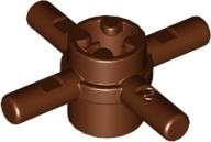
opted to use a spoked interface to achieve the periodic dial-advancing
engagement; the readily available small spoked pieces I could find were
2-bladed, 3-bladed, and 4-bladed. Of these, the best combination I came up with
was the “Technic Pin Joiner Round with Four Bars 1L” (which during the
engagement that occurs with every revolution will advance 90 degrees, or 1
blade, for a 1:4 reduction), plus a 16-to-40 tooth gear interface (for an
additional 1:2.5 reduction – for a total of 1:10!).
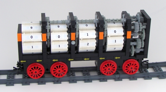
Brickbuilt “panels” were attached to technic chain links wrapped around the
10-tooth link gear. Labels were made using a Casio EZ-Label Printer with 9mm
white tape.
Which Drive Wheels Should be Used?
This question plagued me right up to the end of the project. Clearly the wheel
needed to be compatible with LEGO track layouts, and it had to accept an axle so
it can interface with the rest of the system.
On one hand a larger wheel – like a BBB wheel – provides a larger moment around
the central axis when running. This larger moment could help overcome any
friction in the gear train and prevent wheel slipping, ensuring a high level of
accuracy. On the other hand, it’s not an official LEGO part.
Alternatively, the new LEGO Power Functions drive wheel – with its rubber band
for additional friction – was an appealing option. Besides being an official
part the rubber band promised a no-slip advantage. Even after I had built the
entire design using BBB wheels, I couldn’t help thinking that maybe I should use
the Power Functions wheels instead, so I started working on the analysis
required to incorporate them. I needed to know the “official” running diameter
of the wheel for all subsequent gear train calculations, so I enlisted the
assistance that greatest purveyor of LEGO-related trivia, minutiae, and detailed
information, Dave Eaton. While he sought out official word, he conducted some
bench tests in his own kitchen. During these tests he noted that the rubber
bands, while they themselves never slipped against the track, did at times slip
against the wheels. That is, the rubber bands could rotate independently of
the wheel axle – which is an unacceptable feature when rotational integrity is
paramount! Suddenly my choice was much easier – official wheels were off the
design board, and the BBB wheel design could stand!
Coincidentally, the larger wheels have another advantage. Because they rotate
fewer times per linear distance traversed, the required gear reduction is less.
This generally equates to (a) shorter computational times in the optimization
program, and (b) fewer gears in the reducing gear train, which is easier to
package and introduces less lash into the system.
Calculating the Gear Train.
This was really the meat and potatoes of the exercise. To what level of
accuracy could LEGO gears translate a wheel’s rotation into a real-world measure
of distance? This calculation starts at the beginning; the drive wheels. Using
a pair of calipers I took a series of measurements of the BBB wheel diameters.
Not-so-coincidentally, my measurements matched Ben’s cited 30.4mm drive diameter
extremely well, so that number was confirmed to my satisfaction.
Based on my initial estimates of how far a train might travel in a show, I knew
I wanted the readout to have a display range greater than 10 miles. At the same
time I also wanted to ensure that an astute viewer could actually see some
change in the odometer as the train travelled. The former requirement argued
for pushing the readout into the higher places, while the latter argued for
pushing it into the lower places. Between these two competing philosophies I
settled on a range of 99.99 miles. That is, the highest dial would display the
tens, and the lowest dial would display the hundredths.
The next step was to figure out how many rotations the wheels would make if they
were to travel the distance represented by one full revolution of the
smallest-place dial. As I had settled upon hundredths as the smallest increment
of measurement, a full rotation of that dial represents one-tenth of a mile.
Therefore the target gear reduction could be calculated by determining how many
times the drive wheel would rotate, n, over the course of one tenth of a linear
mile of travel; this then becomes the target gear reduction 1:n.
In order to obsessively optimize the accuracy of the gear reduction, I left
nothing to chance. I wrote a Visual Basic program that would semi-brute-force
through all of the possible combinations of gear reductions that can be achieved
using standard LEGO parts, and continuously retain the combination that produced
the smallest error as compared to the target gear reduction. I refer to the
method as only “semi-brute-force” in that the program utilized several criteria
on the basis of which it would rule out various combinations. For one, the
program was limited only to “clean” gear combinations, or ones that would
interface smoothly; no 14-tooth bevel gear meshed to a 24-tooth spur gear. For
another, the program would skip combinations that were getting progressively
worse; if an additional 1:8 reduction overshot the target reduction by more than
the current error, the program would automatically skip 1:12, 1:16, 1:20, 1:24,
1:36, and 1:40.
With the BBB wheels and a reasonably small target distance (one-tenth of a
mile), the program would run through all of the possible combinations and come
up with a solution within about 15 minutes. I also tested the design envelope –
using the small BBB wheels and a 1-mile distance increment, the calculation took
just over 2 days to cycle through all of the allowed combinations!
At the end of this exercise, a gear train with the greatest possible accuracy
was identified. Even so, this was not necessarily the exact one I would
incorporate. Because there are often multiple combinations that can produce the
same reduction using standard LEGO gearing, I would manipulate the results to
maintain the same overall ratio but optimize the actual part selection. For
example, I might replace a 12:20 and 20:36 pair of reductions with a single
12:36 or 8:24, or vice versa. Various design considerations informed these
substitutions. In general, it was preferable to reduce the number of gears, so
as to minimize lash. Similarly, I tried to minimize the number of 8:x gear
reductions, as I’ve never been pleased with the amount of lash when using an
8-tooth gear. Furthermore, the 40-tooth gear could only be used sparingly, as
it would have to be aligned near the center of the car body in order to keep the
overall car size down.
Still, the final results were impressive and pleasing. Given the assumptions
that went into the calculations (no slip on the track, all gear lash taken up,
and accurate wheel diameter measurements) I was able to achieve an actual gear
reduction that had an error of 0.1423% from the target – or better than 8 feet
per mile. That is, when the dial on the odometer reads 1 mile, the actual
distance gone by the car is 1 mile and 7.5 feet. Not bad! This was
accomplished using a gear train consisting of 1x1:24, 3x12:20, 4x16:24, and
1x8:24 reductions.
And that, as they say … was the easy part. Next came packaging.
One of the original goals was to keep the design as compact as possible. I knew
this would entail packing the gears in as tightly as possible, and that I would
end up going mad if I tried to sort out the optimal design in real brick. I was
not limited to studs-up construction, and I was willing to use offsets as small
as half-stud and single plates. In fact, I might have even tried to do some
fancy SNOTwork to incorporate half-plate offsets if there were a demonstrable
advantage, but fortunately it never came to that.
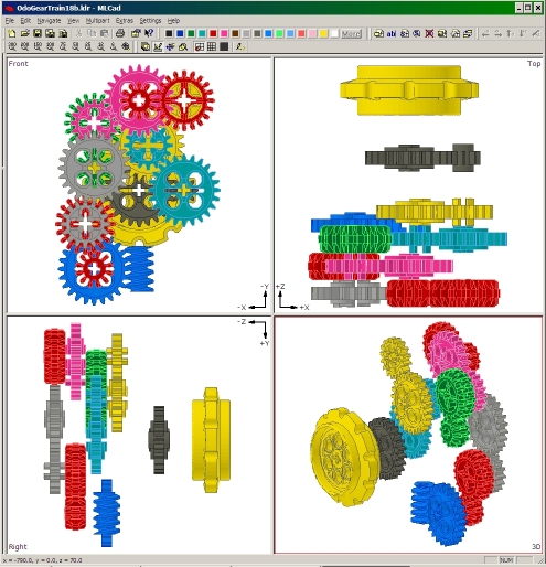
Instead of going mad, I opted for virtual layouts using MLCAD. I can’t
recommend this process enough – especially when working with gear trains in 2 or
3 dimensions. It is much easier to move a gear virtually and check alignments
that to do it in real life, with all of the axle and technic brick rearranging
that entails. Still, my computer shows 39 separate and unique variations on the
gear layout design as I went through the process – and even most of those
represent some evolution as I worked on them.
As much as possible, the large gear reduction pairs were frontloaded toward the
beginning of the entire geartrain. This was an intentional design choice, as I
wanted to make sure that the system developed as much torque as possible as
quickly as possible. This would then allow the friction from the relatively
smooth rolling contact between the BBB wheels and the rails to overcome all of
the gear friction in the train, plus the significant force needed to rotate one
or more of the higher-denomination display wheels.

For the few designs that I did build, the actual construction was
straightforward. Using an MLCAD layout as a schematic, I could assemble the
framework and build the entire assembly from scratch within an hour or so. To
summarize the geartrain design process:
- Determine the contact diameter of the measuring wheels
- Specify the smallest increment size to be displayed
- Run the VB gearing optimization program to determine the best gear reduction
- Manually evaluate and substitute equivalent gear combinations, while retaining the same overall gear reduction
- Use MLCAD to virtually arrange gears into a compact and robust package
- Build real-life gear train according to MLCAD design
This process was repeated many times before the final arrangement was
determined.
Clearly this design uses a large number of gears meshed in series. In order to
reduce the effect of lash in the gearing, all of the dials have a progressing
ratcheting gear; they “click” into place as they advance, and cannot swing back
with vibration or motion. The only exception is the smallest-denomination dial,
which is geared directly to the wheels.
As a direct result of this ratcheting feature, the train is unidirectional; it
will bind up if run backwards. There are a number of arrows on the car to
indicate the proper direction of motion. One benefit of this unidirectional
design is that the slack in the gears should never be a problem. Once the
system has taken up all of its gear lash in the forward direction there is never
any more slack.
What’s Not Ideal?
As Dave Eaton likes to point out, the length of the outside rail on a circular
train track will be longer than the length of the inside rail. This same effect
holds true with nearly all train layouts that are seen in shows; the length of
one of the rails will be longer than the other. So the question becomes – what
do we truly want to measure? The distance the train has gone around the outside
rail? The distance along the inner rail? Or some distance in between?
As implemented right now, the LEGOdometer will measure some distance that lies
between the outer and inner rails, but exactly where in that range cannot easily
be determined. The current design has two outer wheels linked by solid axles to
the two inner wheels; these two axles are then geared together so that their
rotations are tied together. Because the outer rail is longer, some of the
wheels will have to slip when the car goes around a curve. In one extreme case,
it would be the inner wheels that always slipped; in that case, the outer wheels
would remain in perfect contact with the outer rail, and the measured distance
would be that of the outer rail. Conversely, if the outer wheels always slipped
to accommodate the different lengths of the two rails, the measured distance
would correspond to the length of the inner rail. In actuality it is likely a
blend of both inner and outer wheels slipping at different times, creating a
quasi-averaged value that lies somewhere between the two.
A secondary effect to this actually occurs just as the truck enters or exits a
curve. Because both wheel axles are geared together, the leading wheel pair is
forced to rotate at the same speed as the trailing wheel pair. But when the
leading pair has entered the curve while the trailing pair has not, one of the
two pairs (or a combination of both pairs) is slipping. Conversely, the same
thing will happen when the car exits a curve. In theory these effects would
cancel each other out, but if they don’t they could introduce some error to the
measurement.
Ideally, I like the idea of implementing a differential between inner and outer
axles. This would average the length of the two rails, giving a “centerline”
distance traveled. I have assembled a couple versions of a differential
wheelset, but have opted against using it so far since the trucks that house
them are significantly wider.
So How Well Does It Meet the Objectives?
On this score I am pleased! To address each of the objectives in turn:
- Size: having this as a consistent design goal produced great results. The overall dimensions of the “final” design are 10-3/8 L x 2-3/16 W x 4-7/8 inches H (~33 studs L x 8 studs W x 1 5 studs H). Although the car is about 8 studs wide at its widest, much of the body is actually between 6 and 7 studs wide. All told it is small enough to fit in with many 6-wide trains. It is, however, relatively heavy! Even after swapping out all of the regular bricks for lighter technic bricks, it weighs in at 1.47 lbs! This could be an issue if it were part of a long train, but on a moderate length train the motors should have no problem. On the other hand that mass ensures good contact between the wheels and the rails, such that the gear resistance does not induce any unwanted slip in the system.
- Measurement Accuracy: Accurate to within 7.5 feet per mile while measuring a distance that lies somewhere between the inner and outer rails! With an option to swap out the truck for a differential version that specifically measures the mid-rail distance!
- Readability: I’m mostly pleased with this. It’s not quite as intuitive as I’d like, but once someone is told where to look (“read the numbers along the orange markers”) the digits are legible and clear, easy to pick out. The decimal point isn’t quite ideal – in fact, as I’m typing this I’m realizing that it would probably be better to make the decimal dials in a different color for clarity. Still, with about 10 seconds of instruction anyone would be able to make out the reading, even as it goes by as part of a moving train.
- Durability: Success! I’ve moved this car around all over the place, taken it to show people, brought it into work on multiple occasions, and never had a single piece fall off. It requires one calibration during construction to ensure that all of the gears between the dials are aligned correctly, but from then on it’s simple to reset. I really like that the design is not at all fiddly!
- Standard LEGO only: The exceptions that I’ve made here – BBB wheels, and Tape Labels – were ones I anticipated going into the project. I sleep okay at night with the choices I made.
- No RCX or NXT: Ha! Mindstorms is for cheaters ;)
The total build time was about 2 months, 6 days a week, about an hour a day. So
that comes out to … about 50 hours of actual build time? On top of that, there
were about 10 hours of VB programming, and probably close to 20 hours of MLCAD
geartrain layout work (39 iterations!). Add to that a couple hours of Bricklink
order compilation, various technical investigations, photography and a 3700-word
write-up, and the whole effort tallies up to about 100 hours. Roughly.
Other images are available
here.
So Let’s See it Work!
Done! For the purposes of demonstration I threw together a simple drive stand
that will set the wheels spinning. Here are two short videos: the first shows
the straightforward rotation of the hundredths dial. The second shows the
engagement of all four dials flipping over when the LEGOdometer passes any value
of the form X9.99.
Video 1
Video 2
x-posted to .trains, .technic, www.trains-n-town.com, and www.nelug.org
|
|
| |
In lugnet.announce.moc, Shaun Sullivan wrote:
| |
As is my tendency, here’s an absurdly long treatise describing the
development of a LEGO Train Odometer Car (a.k.a. the “LEGOdometer”).
|
-- Major Snippage! --
Awesome MOC! It was interesting reading about the process you went through in
developing this vehicle. Thank you for sharing this fantastic work with everyone
here.
Cheers,
J.P. Manalo
|
|
| |
In lugnet.announce.moc, Shaun Sullivan wrote:
| |
As is my tendency, here’s an absurdly long treatise describing the
development of a LEGO Train Odometer Car (a.k.a. the “LEGOdometer”).
|
snip
Great idea! Tempting to build something similar for our next show...
The only disappointing part of the story is that it took a number of days of
computing power to come up with a solution that doesn’t use computing power ;-)
|
|
| |
In lugnet.announce.moc, Shaun Sullivan wrote:
| |
As is my tendency, here’s an absurdly long treatise describing the
development of a LEGO Train Odometer Car (a.k.a. the “LEGOdometer”).
|
Insane. Amazing. Shock. Awe. (and Spotlight.)
|
|
| |
In lugnet.technic, Philippe Hurbain wrote:
> Very impressive! I don't know what is the most amazing: the odometer
> itself or the extensive write-up ;o)
Thanks! Both were fun ;)
> Would you have more details (MLCad?) of the gearing/ratcheting between dials?
I don't yet, though I can easily do that. The 4-spoked technic joiners, when
turned, rotate the 16T gear at the opposite end of the dial. That gear then
connects to two idler gears which drive a 40T gear; that 40T gear then connects
through the framework to the next dial.
The ratchet mechanism is simply a rack gear on a loose technic pin that
interfaces with the 40T gear to ensure that it only rotates in one direction.
I'll see what I can do about modeling it.
> And BTW, did you see this:
I had not seen that. It's ... it's ... it's gorgeous! I'm stunned. I've been
staring at it all morning, dissecting it, and ithcing to get home and build a
version. I think this would work better than my cog-and-pin method, and I'm
dying to try and implement this right away. I love the aesthetics of its
functioning.
Thanks for the link! I expected a longer downtime before Rev. 2.0, but I don't
think I can wait.
|
|
| |
In lugnet.technic, Ronald Vallenduuk wrote:
| |
In lugnet.announce.moc, Shaun Sullivan wrote:
| |
As is my tendency, here’s an absurdly long treatise describing the
development of a LEGO Train Odometer Car (a.k.a. the “LEGOdometer”).
|
snip
Great idea! Tempting to build something similar for our next show...
The only disappointing part of the story is that it took a number of days of
computing power to come up with a solution that doesn’t use computing power
;-)
|
Tom Atkinson pointed out that same thing ... it’s something that never even
struck me while I was working on it. The irony just makes it all the more
ridiculous, in a fun way!
|
|
| |
In lugnet.announce.moc, Shaun Sullivan wrote:
| |
As is my tendency, here’s an absurdly long treatise describing the
development of a LEGO Train Odometer Car (a.k.a. the “LEGOdometer”).
|
Interesting. I thought this might be interesting to use in our displays...until
I read that it binds up in reverse. When we lose a car for whatever reason
(often some young kid’s hand straying where it ought not to), we usually
recouple by running the train in reverse to pick up the stragglers. Perhaps
your next iteration could have a slip gear system that disengages in reverse and
engages when going forward?
| |
As Dave Eaton likes to point out, the length of the outside rail on a
circular train track will be longer than the length of the inside rail. This
same effect holds true with nearly all train layouts that are seen in shows;
the length of one of the rails will be longer than the other. So the
question becomes – what do we truly want to measure? The distance the train
has gone around the outside rail? The distance along the inner rail? Or
some distance in between?
|
I would think it would measure the outer rail at high speeds and the inner rail
at slow speeds. The reasoning is that at slow speeds, assuming the motor bogey
is pulling rather than pushing, it will pull the train against the inside rail
so there will be more friction on that side of the bogeys. At high speeds,
however, momentum comes into effect, and if you’ve ever watched a LEGO train
moving at significant speed, anything but the most lightweight of cars will heel
over a bit when it slams into the curve, so the inner wheels will actually lose
contact with the rails for a bit as they lift up, while the outer wheels will be
pressed into the rail.
|
|
| |
In lugnet.announce.moc, Shaun Sullivan wrote:
| |
As is my tendency, here’s an absurdly long treatise describing the
development of a LEGO Train Odometer Car (a.k.a. the “LEGOdometer”).
|
Your “LEGOdometer” is amazing! I especially liked hearing about the design
process and the fact that the final product is purely mechanical. I’d never be
able to design something like this...
-Bryan
|
|
| |
Shaun,
Impressive work, both in construction and the write up! Welcome back to the
fold of trains (at least for a little bit)...did you know that the next National
Train show (that ILTCO has been particpating heavily since 2005) will be in
Hartford for 2009?
I can’t say enough about your MOC.. in fact, I don’t have time to read (or
comprehend it) while at work, so I’ll have to look at it more in detail later.
Ever think about doing an article about this for BrickJournal?
Scott Lyttle
|
|
| |
A nice explanation and reading. A better MOC.
Also intend to return later and read it more carefully. It is extensive, to get
everything at first. ;)
|
|
| |
In lugnet.announce.moc, Shaun Sullivan wrote:
| |
As is my tendency, here’s an absurdly long treatise describing the
development of a LEGO Train Odometer Car (a.k.a. the “LEGOdometer”).
|
--snip (as is my own tendency ;) )--
Wow. I imagine if I had a clue how to build technic there’d be a few more wows
but you can tattoo me impressed as is.
Tim
|
|
| |
> I'll see what I can do about modeling it.
It would certainly help my slow mind ;o) Though I think I got it through your
explainations.
>
> > And BTW, did you see this:
>
> I had not seen that. It's ... it's ... it's gorgeous! I'm stunned. I've been
> staring at it all morning, dissecting it, and ithcing to get home and build a
> version. I think this would work better than my cog-and-pin method, and I'm
> dying to try and implement this right away. I love the aesthetics of its
> functioning.
Very elegant and parts savvy, but I am not sure it would provide a design as
compact as yours.
>
> Thanks for the link! I expected a longer downtime before Rev. 2.0, but I don't
> think I can wait.
Sorry to disturb you ;o)
Philo
|
|
| |
Shaun,
OK, I’m not a train guy and or even a moderately skilled Technic guy, but it’s
easy to see that this is officially ridiculously awesome.
I’ve become interested in incorporating Technic functionality into minifig scale
MOCs, but I don’t think it would have occured to me that you can get this sort
of complexity into such a small compact space. Puts my Bridgelayer to shame, if
I do say so myself.
Brilliant.
Magnus
|
|
| |
In lugnet.technic, David Laswell wrote:
| |
In lugnet.announce.moc, Shaun Sullivan wrote:
| |
As is my tendency, here’s an absurdly long treatise describing the
development of a LEGO Train Odometer Car (a.k.a. the “LEGOdometer”).
|
Interesting. I thought this might be interesting to use in our
displays...until I read that it binds up in reverse. When we lose a car for
whatever reason (often some young kid’s hand straying where it ought not to),
we usually recouple by running the train in reverse to pick up the
stragglers. Perhaps your next iteration could have a slip gear system that
disengages in reverse and engages when going forward?
|
That’s something I hadn’t considered. Fortunately, unless it’s run backwards
for a long time, it probably won’t be an issue. It takes a good while to take
up the lash in all of the gears in the opposite direction; the overall gear
reduction is 1:1685.099 over 9 different gear pairs. That translates to plenty
of distance before the hundreths wheel starts runing in reverse.
On top of that, the first ratchet is actually on the second dial, the tenths
place. As a result the gear train won’t actually bind up until the engagement
on the tenths dial has run backwards and tries to turn the spoked pin joiner
backwards.
Short story: it’s unlikely that the car will bind up unless it’s running
backwards for a while.
| |
| |
As Dave Eaton likes to point out, the length of the outside rail on a
circular train track will be longer than the length of the inside rail.
This same effect holds true with nearly all train layouts that are seen in
shows; the length of one of the rails will be longer than the other. So the
question becomes – what do we truly want to measure? The distance the train
has gone around the outside rail? The distance along the inner rail? Or
some distance in between?
|
I would think it would measure the outer rail at high speeds and the inner
rail at slow speeds. The reasoning is that at slow speeds, assuming the
motor bogey is pulling rather than pushing, it will pull the train against
the inside rail so there will be more friction on that side of the bogeys.
At high speeds, however, momentum comes into effect, and if you’ve ever
watched a LEGO train moving at significant speed, anything but the most
lightweight of cars will heel over a bit when it slams into the curve, so the
inner wheels will actually lose contact with the rails for a bit as they lift
up, while the outer wheels will be pressed into the rail.
|
That’s another good point. Based on your observation at high speeds even a
differential won’t be truly accurate; in fact, it could be much worse! If the
inner wheels lose contact altogether, then an averaging differential will give a
value between “fast” and “stop” - which would correspond to a much smaller
distance than even the inner rail alone would produce.
Hmmm, that might be a good argument to stick with the solid axle!
|
|
| |
In lugnet.technic, Scott Lyttle wrote:
| |
Shaun,
Impressive work, both in construction and the write up! Welcome back to the
fold of trains (at least for a little bit)...did you know that the next
National Train show (that ILTCO has been particpating heavily since 2005)
will be in Hartford for 2009?
|
Yep, I heard about that a couple of months ago ... I’m looking forward to it and
plan on being there. It’ll be great to participate in a show that also has lots
of representation from clubs outside of New England!
|
|
| |
Shaun Sullivan wrote:
> That's another good point. Based on your observation at high speeds
> even a differential won't be truly accurate; in fact, it could be
> much worse! If the inner wheels lose contact altogether, then an
> averaging differential will give a value between "fast" and "stop" -
> which would correspond to a much smaller distance than even the inner
> rail alone would produce.
A differential might have other problems. I seem to recall that use of
differentials was explored in geared locomotives (such as Shay, Climax, and
Heisler), and was abandoned because the differential caused power loss in
curves. (reference here: http://climaxlocomotives.com/history/ ). Not sure
if that would translate in reverse to an issue.
Frank
|
|
| |
In lugnet.announce.moc, Shaun Sullivan wrote:
| |
As is my tendency, here’s an absurdly long treatise describing the
development of a LEGO Train Odometer Car (a.k.a. the “LEGOdometer”).
|
Great work sir! You had me at the counter mechanism, but making it a train car,
wow!
Cheers
DRS
|
|
| |
Hey Shaun,
That’s so freakin’ crazy awesome insane mega uber brainy bada**!
I tip my Acme Brain Massager to you, sir!
Dave S.
|
|
| |
In lugnet.technic, Frank Filz wrote:
> A differential might have other problems. I seem to recall that use of
> differentials was explored in geared locomotives (such as Shay, Climax, and
> Heisler), and was abandoned because the differential caused power loss in
> curves. (reference here: http://climaxlocomotives.com/history/ ). Not sure
> if that would translate in reverse to an issue.
Well, if a real train hits curves in any manner similar to how a LEGO train
does, then the inside wheel will probably lift up enough to at least slip on the
rail, which would result in that very effect. On the plus side, as it loses
power, it will lose speed, and the inner wheel will sit more firmly on the rail,
thus allowing it to pick up speed again. :D
|
|
| |
In lugnet.technic, David Laswell wrote:
| |
In lugnet.announce.moc, Shaun Sullivan wrote:
| |
As is my tendency, here’s an absurdly long treatise describing the
development of a LEGO Train Odometer Car (a.k.a. the “LEGOdometer”).
|
Interesting. I thought this might be interesting to use in our
displays...until I read that it binds up in reverse. When we lose a car for
whatever reason (often some young kid’s hand straying where it ought not to),
we usually recouple by running the train in reverse to pick up the
stragglers. Perhaps your next iteration could have a slip gear system that
disengages in reverse and engages when going forward?
|
First off, “wow!” A great idea, what sounds to be a very thorough design (and
documentation), and an aesthetically pleasing package.
A few thoughts, suggestions, and so forth. First, while the videos are
impressive, I wonder if the performance on the dynamometer is representative. In
the videos you are driving the counter with a rubber tire, with a much higher
coefficient of friction than you would find on track. I’ve found that the BBB
wheels can slip around curves, especially if they are tied together and pushing
a bit of a load. So you might wind up measuring a distance even shorter than the
inside rail with your current design. If you want precision, I’d suggest using a
rubber wheel (actually a few rubber wheels in a cylinder like arrangement)
pressing down on the top of the rail, with a technic shock absorber or some
other spring to keep the pressure on, e.g., some combination of:


Make the cylinder of tires wide enough to catch all curves, placing it as near
as possible to the flanged wheels to keep the width down (or even better, devise
a dynamic system such that it will swing out/in on curves as needed, grin). And
to avoid the fact that one rail is longer than the other on curves, orient the
tires such that they are only on one rail.
As far as ease of reading, I think a face that only shows the current readout
would drive that point home. But it would be a shame to hide all of the eloquent
mechanics under a cover. So at most, just cover the side showing the reading,
leaving the top and back open to show off the workings. Or better, just build a
two wide ring around the actual readout.
As for a train club not wanting to run the car, you could easily put it at the
rear of the train so that you never have to back up. Or pull the partial train
forward, pull the odometer car out, then go retrieve the other half of the
train. It is cool enough that any club would be crazy not to make accommodations
for it.
Very nice,
Benn
|
|
| |
This would make a nice article for RailBricks and possibly with some
instructions.
M
|
|
| |
In lugnet.technic, Shaun Sullivan wrote:
| |
That’s something I hadn’t considered. Fortunately, unless it’s run backwards
for a long time, it probably won’t be an issue. It takes a good while to
take up the lash in all of the gears in the opposite direction; the overall
gear reduction is 1:1685.099 over 9 different gear pairs. That translates to
plenty of distance before the hundreths wheel starts runing in reverse.
|
True, but then you’re losing the count on some of the distance traveled. I
thought of a better option to all of this, though. I can’t remember who it was,
but someone (don’t even ask me to remember who, or where to find this) came up
with a gear system that turned +/- input into + output. That is, regardless of
which way you turned the input source, the output constantly turned in one
direction. Incorporating this into your design would allow the odometer to
continue adding in both directions, though you would have to remember to make
sure you faced the correct side outwards.
| |
On top of that, the first ratchet is actually on the second dial, the tenths
place. As a result the gear train won’t actually bind up until the
engagement on the tenths dial has run backwards and tries to turn the spoked
pin joiner backwards.
Short story: it’s unlikely that the car will bind up unless it’s running
backwards for a while.
|
Is this something that would make a difference based on how recently it has
flipped the tenths dial? For example, if it has just flipped the dial far
enough to trip the turnback catch mechanism, will running it backwards result in
a significantly shorter distance to where it binds than if it was just on the
verge of pushing the dial past the catch?
|
|
| |
In lugnet.technic, Shaun Sullivan wrote:
> In lugnet.technic, Philippe Hurbain wrote:
> > And BTW, did you see this:
>
> I had not seen that. It's ... it's ... it's gorgeous! I'm stunned. I've been
> staring at it all morning, dissecting it, and ithcing to get home and build a
> version. I think this would work better than my cog-and-pin method, and I'm
> dying to try and implement this right away. I love the aesthetics of its
> functioning.
>
> Thanks for the link! I expected a longer downtime before Rev. 2.0, but I don't
> think I can wait.
I'd love to see what you come up with! however I fear Philo may be right about
it being too large.
Your mechanism is shorter at 3 studs (2 cogs and a support) my chain precession
drive is 4 studs long. Also the precession mechanism needs 9 studs clearance to
turn vertically (8.5 to be exact) and 8 studs horizontally, and this may make it
too big for a train!
The precession mechanism turns in both directions, but it does favour one
direction, this is due to the chain tread link being offset (not in the middle
between the chain pivot pins) It does need to be aligned well to run smoothly,
which makes me think your cog method is more robust. Chain alignment can be
tricky also there are 44 chain link bars and forty teeth, meaning that one or
two links out, and it will not give enough tick over turn at the right point.
even running the chain the other way makes a difference (because of the offset)
I like your number drums better than mine! and agree that a tick makes for a far
better counter! as for readability you could screen off the dials leaving only a
slot to read from, and yes colours for complete and partial miles.
If you were to use the precession mechanism you could place your number stickers
directly on the track links, making smaller dials, and making screening them
easier.
Its a nice project!
Regards
Mike.
|
|
| |
Nice box !
I ran most ratios through a pathetic microsoft product to derive a comparible
metric read-out for those that made the transition from the stone age.
put simply:
1 1:12
3 20:36
1 16:24
produces 1:104.9 at 95.5mm per rotation
or for every 10.026 meters.
2.6 meters error per Kilometer.
I only ran declining ratios to a factor of 8, so there may be a result with less
error using either more sequences or a combination of delining and increasing
torque combinations.
I’ll try to put one together for the next SLTC show using two cars.
The lead car showing kilometers, the trailing car to show 100ths and 10s of
meters plus hold the gear box.
I imagine the same could be done to calculate yards, lightyears or parsecs if so
inclined....
hm, the same BB wheel would need to turn 99,058,539,174,952,789 times to travel
a lightyear...
Steve
|
|
| |
In lugnet.technic, Stump Dunn wrote:
| |
I ran most ratios through a pathetic microsoft product to derive a comparible
metric read-out for those that made the transition from the stone age.
|
Don’t you mean those who reverted back to the stone age? I mean, the metric
system is based entirely on being able to calculate stuff using your fingers,
where the Imperial System requires better multiplication skills than your
average monkey is likely to possess.
|
|
| |
| |
system is based entirely on being able to calculate stuff using your fingers,
|
Beats a system based entirely on units of toes !
Steve
|
|
| |
In lugnet.technic, Stump Dunn wrote:
| |
I ran most ratios through a pathetic microsoft product to derive a comparible
metric read-out for those that made the transition from the stone age.
put simply:
1 1:12
3 20:36
1 16:24
produces 1:104.9 at 95.5mm per rotation
or for every 10.026 meters.
2.6 meters error per Kilometer.
I only ran declining ratios to a factor of 8, so there may be a result with
less error using either more sequences or a combination of delining and
increasing torque combinations.
|
I ran my VB program and came up with the following:
7 x 20:36
7 x 16:24
which produces an error of 0.991 meters per kilometer.
Of course, packaging that many gears is probably a bit challenging ... but I’ll
bet you can do it ;)
|
|
| |
In lugnet.technic, Shaun Sullivan wrote:
> In lugnet.technic, Philippe Hurbain wrote:
> > Very impressive! I don't know what is the most amazing: the odometer
> > itself or the extensive write-up ;o)
>
> Thanks! Both were fun ;)
>
>
> > Would you have more details (MLCad?) of the gearing/ratcheting between dials?
>
> I don't yet, though I can easily do that. The 4-spoked technic joiners, when
> turned, rotate the 16T gear at the opposite end of the dial. That gear then
> connects to two idler gears which drive a 40T gear; that 40T gear then connects
> through the framework to the next dial.
>
> The ratchet mechanism is simply a rack gear on a loose technic pin that
> interfaces with the 40T gear to ensure that it only rotates in one direction.
>
> I'll see what I can do about modeling it.
Even with that explaination, I just can't seem to get the spacing and the
gearing right between the dials. If you have the time, please, I would like a
visual aid of the between walls and the between-dials gearing. When I first saw
this, I thought "wow, sooo cool! I have to build one for my modest layout!".
Several months of tinkering with LDraw and real pieces, and I'm still stuck
after the first dial setup.
|
|
|