| |
I wish TLC would make these parts. Seeing earlier discussions I think I’m not
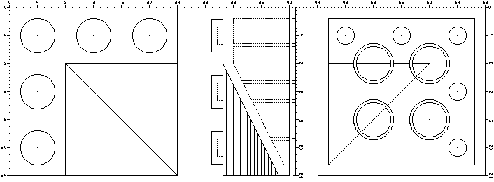
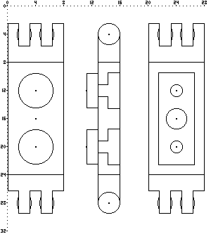
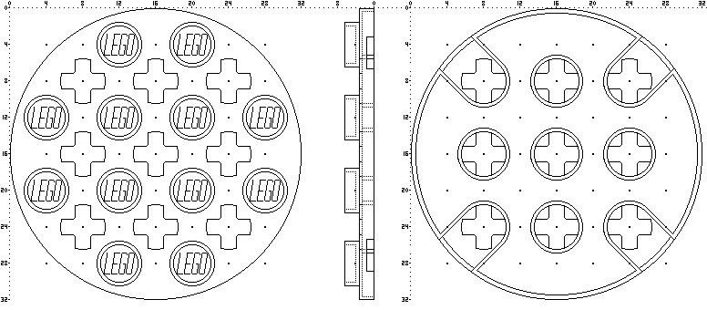
alone! I’ve attempted 3rd angle projection drawings, showing top, side and
underside, despite not having a drawing package. Drawing these parts in Paint
is eyestrain city!
The numbers along the edges are measurements in millimetres, assuming 8mm to a
stud. I drew the parts at 16 pixels per millimetre, to get plenty of detail.
3x3 33 degree inner corner slope brick:
http://www.brickshelf.com/gallery/mbellis/New-Parts/Designed-Only/Slopes/33_deg_inner_corner_slope.bmp
1x2 hinge plate, sadly made as obsolete as its single-ended cousins by
click-hinges:
http://www.brickshelf.com/gallery/mbellis/New-Parts/Designed-Only/Plates/1x2_hinge_plate.bmp
I originally wanted this piece for mudguards on technic vehicles, to remove the
need to use pairs of single-ended hinges to form the curve over the wheel.
4x4 round plate with extra holes. The holes allow two or four round bricks to
be supported by axles through the plate and also allow 4-wide cylinders to be
made without technic peg holes in the sides, from the bricks you’d otherwise
use:
http://www.brickshelf.com/gallery/mbellis/New-Parts/Designed-Only/Plates/4x4_round_plate.bmp
(For TLC’s benefit, the holes also save on raw plastic!)
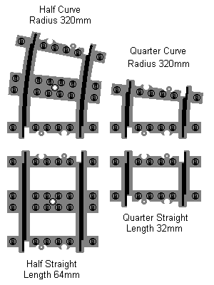
For train fans, a few shorter track pieces, both curved and straight:
http://www.brickshelf.com/gallery/mbellis/New-Parts/Designed-Only/Trains/new_track_pieces.bmp
These would open the geometrical possibilities right up! Ideally they’d be
supplied in packs of eight pieces each. I would certainly buy several packs of
each, as long as they were the same colour as the rest of the track.
When I met Jake, he encouraged me to share these ideas for parts. After all,
there’s no shortage of new parts coming from TLC every year, so why not let some
of them be ones that will be more useful to AFOLs? If you have any drawings of
your own prospective new parts, I’d encourage you to share them too. I propose
these as parts for TLC to make. Please indicate which of them you would find
useful.
Another time, I might draw a few of the parts that I’ve made from existing ones
- the tried and tested selection!
PLMKWYT
Mark
|
|
| |
In lugnet.parts.custom, Mark Bellis wrote:
| |
I wish TLC would make these parts. Seeing earlier discussions I think I’m
not alone!
|
Mark,
You are most definitely not alone. :)
I’m guessing one of the earlier discussions you might be referring to would be
this one:
http://news.lugnet.com/dear-lego/?n=4837
I must admit, I love this topic. I think as much effort, if not more,
should go into which parts the company decides to make as what goes into any
given set they then create with those parts.
Here was my own contribution to that above noted thread:
http://news.lugnet.com/dear-lego/?n=4872
I’ve since decided that a standard 3x3 plate would also be good... to go with
the brick pictured there. :)
| |
I’ve attempted 3rd angle projection drawings, showing top, side
and underside, despite not having a drawing package. Drawing these parts in
Paint is eyestrain city!
|
I like the way you’ve done your drawings. I love the ‘blueprint’ feel to them.
Reminds me of the drawings included with the original patent application
submitted by LEGO.
In fact, that’s part of what I think of when imagining what a new part might
look like. I wonder, “would this part fit into the LEGO system back in 1958?
How about 1978? How about today?” In other words... can new parts be created
that have that ‘classic’ look to them? Can they look as though they have been
part of the system since the beginning? I think, sometimes, the answer is yes.
This is obviously a perfect example of what I mentioned above. Such a slope
could have/should have existed for many years. I like the fact that you’ve gone
to such trouble to illustrate what it would look like. It doesn’t seem like
that much of a stretch to produce it, now does it? :)
Very cool, and I think fits with what I mentioned earlier... classic look!
| |
there’s no shortage of new parts coming from TLC every year, so why not let
some of them be ones that will be more useful to AFOLs?
|
I think ‘classic’ parts, like the ones you’ve shown above, could appeal to all
builders.
| |
If you have any
drawings of your own prospective new parts, I’d encourage you to share them
too. I propose these as parts for TLC to make. Please indicate which of
them you would find useful.
|
For a long time now, I’ve also thought this would make a great contest. Plain
and simple, “Design your own LEGO element”. Maybe a nice consolation for those
of us who still can’t run LDD on our computers. :)
Mark, thanks for bringing this topic back to life again!
Best regards,
Allan B.
The LEGO Builder’s Guide
|
|
| |
| |
Another time, I might draw a few of the parts that I’ve made from existing
ones - the tried and tested selection!
PLMKWYT
Mark
|
Very cool--I’ll take those over new Bionicle parts any day. I can see the
victorian porches now with that sloped brick...
I wonder if you could add this to your part list, I was just thinking about this
yesterday...here’s what I had--I can only go via description here.
First, you have this part:
www.peeron.com/inv/parts/6215 (2x3 brick with curved top)
Now, could this part:
www.peeron.com/inv/parts/3675
be modified to a rounded curve instead of a 33 degree slope?
The idea, instead of using a 33 degree corner slope, have a corner more
rounded--looks more like those aluminum awnings used on older homes.
-Scott Lyttle
|
|
| |
In lugnet.parts.custom, Mark Bellis wrote:
| |
I wish TLC would make these parts. Seeing earlier discussions I think I’m
not alone! I’ve attempted 3rd angle projection drawings, showing top, side
and underside, despite not having a drawing package. Drawing these parts in
Paint is eyestrain city!
|
(with random snippage)
Your drawings are excellent! What detail!
All of your ideas (and that of the earlier, similar posts) are good. But, I’m
not sure what this could be used for, although ANY 4x4 round plate would be
welcomed, with or without the axle holes.
| |
I’d encourage you to share them
too. I propose these as parts for TLC to make. Please indicate which of
them you would find useful.
Another time, I might draw a few of the parts that I’ve made from existing
ones - the tried and tested selection!
PLMKWYT
Mark
|
This is a great topic/post! Spotlighted!
How about a regular 2x2 brick, with 2 studs on each side? It would be similar to
this, but larger:

Also, (and I don’t mean to hijack this thread), but why is TLC able to produce
new molds for parts each year, but cannot seem to fix or replace their older
molds, such as that for the cypress tree, or the 1x1 ‘window’ brick? I’d prefer
the availability of previously-made parts, rather than new ones.
With an open can of worms in hand, :)
Nelson
|
|
| |
In lugnet.parts.custom, Mark Bellis wrote:
| |
I wish TLC would make these parts. Seeing earlier discussions I think I’m
not alone! I’ve attempted 3rd angle projection drawings, showing top, side
and underside, despite not having a drawing package. Drawing these parts in
Paint is eyestrain city!
|
YIKES!
Well, OK, this is what I need for my students to model parts in AutoCAD! I tried
this one because it looked the easiest; I’ll do the others if there’s interest.
I don’t know if anyone else has mocked these up already..
It took me about 10 minutes, but mainly because I had to figure out how STL2DAT
worked (I usually use 3DWin, but it didn’t do such a great job). It looks OK in
MLCAD, but I know it’s pretty messy.. I guess good enough to throw a MOC
together for fun.
http://www.brickshelf.com/cgi-bin/gallery.cgi?f=115617
Darrell
|
|
| |
In lugnet.parts.custom, Scott Lyttle wrote:
| |
...
I wonder if you could add this to your part list, I was just thinking about
this yesterday...here’s what I had--I can only go via description here.
First, you have this part:
www.peeron.com/inv/parts/6215 (2x3 brick with curved top)
Now, could this part:
www.peeron.com/inv/parts/3675
be modified to a rounded curve instead of a 33 degree slope?
The idea, instead of using a 33 degree corner slope, have a corner more
rounded--looks more like those aluminum awnings used on older homes.
-Scott Lyttle
|
OK, so the piece is like this:
1. The base is 3x3.
2. Is the corner a right angle, an 8mm radius curve, or a 16mm radius curve,
like this piece? http://www.peeron.com/inv/parts/30357
3. I assume it has 2x2 studs on top, as if two 2x3s with curved top had been
superimposed at right angles.
4. Is the curved edge continuously smooth round the corner or is there a
diagonal edge where the two curved slopes meet?
Mark
|
|
| |
In lugnet.parts.custom, Nelson Yrizarry wrote:
| |
Your drawings are excellent! What detail!
|
Thanks, I like to do a proper job :-)
| |
All of your ideas (and that of the earlier, similar posts) are good. But, I’m
not sure what this could be used for, although ANY 4x4 round plate would be
welcomed, with or without the axle holes.
|
Up to now, there is no plate to go with the 4x4 round brick and the half
cylinders. This means that unless your round bricks have exactly 4 bricks
between them, you can’t support them at the side with a technic beam or similar,
by putting pegs in the holes and a beam up the side.
With my 1:20 scale Apache helicopter, I used 4x4 round bricks for the rocket
launchers. I wanted to put two 4x4 round bricks 7 plates apart, in order to
support them with pegs on a pair of 1x5 technic plates with holes in the ends,
which attach the rocket launchers to the ‘wings’. Since there is no 4x4 round
plate I’ve had to use 2x2 round plates for now.
| |
| |
I’d encourage you to share them
too. I propose these as parts for TLC to make. Please indicate which of
them you would find useful.
Another time, I might draw a few of the parts that I’ve made from existing
ones - the tried and tested selection!
PLMKWYT
Mark
|
This is a great topic/post! Spotlighted!
How about a regular 2x2 brick, with 2 studs on each side? It would be similar
to this, but larger:
|
Hmmm...
How about a 1x1 brick with studs on two adjacent sides instead? You could use 4
of those to make your 2x2, but the source brick would be smaller and more
versatile. Even better if the other 2 sides had a shallow technic peg hole in
them, which could also accept a stud from another similar brick. Then you could
make 2x3, 3x3, 2x4, 4x4,... any size you like!
I like the 1x1 with studs on opposite sides, since it is the complement of the
1x1 technic beam. I will use both to support letters in models, like this:
http://www.brickshelf.com/cgi-bin/gallery.cgi?i=742620 Using them alternately,
with the vertical tiles of the letters pointing alternately left and right.
| |
Also, (and I don’t mean to hijack this thread), but why is TLC able to
produce new molds for parts each year, but cannot seem to fix or replace
their older molds, such as that for the cypress tree, or the 1x1 ‘window’
brick? I’d prefer the availability of previously-made parts, rather than new
ones.
With an open can of worms in hand, :)
Nelson
|
Yes, those little windows would be useful, and also their taller cousins. I
would use them in steam locos.
A mould does a certain number of parts, but is very expensive to make.
Therefore if one was made for the 1x1 windows, you’d have to run off a huge
number of them, requiring them to be used in a set. I think a mould makes about
12 2x4s at a time, so probably 20 window frames. Then it does at least 100,000
cycles. The trouble with the windows is that the panes are separate and have to
be glued in. That’s labour intensive, making them even more expensive to
produce. Would you be prepared to pay $1 each for them and buy by the thousand?
:-)
Mark
|
|
| |
In lugnet.parts.custom, Darrell Urbien wrote:
| |
In lugnet.parts.custom, Mark Bellis wrote:
| |
I wish TLC would make these parts. Seeing earlier discussions I think I’m
not alone! I’ve attempted 3rd angle projection drawings, showing top, side
and underside, despite not having a drawing package. Drawing these parts in
Paint is eyestrain city!
|
YIKES!
Well, OK, this is what I need for my students to model parts in AutoCAD! I
tried this one because it looked the easiest; I’ll do the others if there’s
interest. I don’t know if anyone else has mocked these up already..
It took me about 10 minutes, but mainly because I had to figure out how
STL2DAT worked (I usually use 3DWin, but it didn’t do such a great job). It
looks OK in MLCAD, but I know it’s pretty messy.. I guess good enough to
throw a MOC together for fun.
http://www.brickshelf.com/cgi-bin/gallery.cgi?f=115617
Darrell
|
Are you doing 3rd angle projection or 3D?
10 minutes is a lot less than it took me in Paint. I suppose once you’re
trained in AutoCAD, a lot of things are quick.
Could you post jpegs of the results?
I created bits like studs in the drawing and did a lot of copying and pasting.
getting them to line up well with a limited screen size was the main problem in
Paint. I suppose the CAD packages automatically line things up for you.
Mark
|
|
| |
In lugnet.parts.custom, Mark Bellis wrote:
| |
In lugnet.parts.custom, Scott Lyttle wrote:
| |
...
I wonder if you could add this to your part list, I was just thinking about
this yesterday...here’s what I had--I can only go via description here.
First, you have this part:
www.peeron.com/inv/parts/6215 (2x3 brick with curved top)
Now, could this part:
www.peeron.com/inv/parts/3675
be modified to a rounded curve instead of a 33 degree slope?
The idea, instead of using a 33 degree corner slope, have a corner more
rounded--looks more like those aluminum awnings used on older homes.
|
4. Is the curved edge continuously smooth round the corner or is there a
diagonal edge where the two curved slopes meet?
|
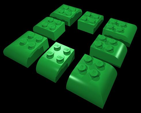
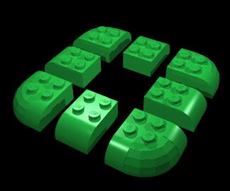
So, like one of these?
http://www.brickshelf.com/cgi-bin/gallery.cgi?i=1090707 Diagonal edge
http://www.brickshelf.com/cgi-bin/gallery.cgi?i=1090761 Round edge
Steve
|
|
| |
In lugnet.parts.custom, Mark Bellis wrote:
| |
I wish TLC would make these parts. Seeing earlier discussions I think I’m
not alone! I’ve attempted 3rd angle projection drawings, showing top, side
and underside, despite not having a drawing package. Drawing these parts in
Paint is eyestrain city!
|
If you’re going to explore these kinds of things, I recommend you learn how to
create LDraw parts (or what’s easier, editing existing ones). It’s really not
that hard. Also in many cases you can get a pretty good approximatin by just
overlapping existing pieces.
--Bill.
|
|
| |
The piece I really want is 2x5 or 1x5 (or x7) bricks and plates. When building
a MOC that’s an odd number of studs wide, you have to either make it
asymmetrical or use x1 and x3 bricks which aren’t good for structural support.
|
|
| |
In lugnet.parts.custom, William R. Ward wrote:
| |
The piece I really want is 2x5 or 1x5 (or x7) bricks and plates. When
building a MOC that’s an odd number of studs wide, you have to either make it
asymmetrical or use x1 and x3 bricks which aren’t good for structural
support.
|
I’ve always found it interesting that 1x3 and 2x3 bricks and plates are the only
odd length elements of those general categories. As you mention, there’s no
1x5, no 2x5, no 1x7, no 2x9 and so on.
I assume this is by design, but then you have to ask the question, “why not just
make them?” I’m not suggesting they dash off to the factory to start churning
out 1x13 bricks, but I think that perhaps the Nx5 and Nx7 pieces could be a
significant addition to what I think of as *classic* elements. i.e. ones that
either were or look like they could have been around since the late 50’s.
Best regards,
Allan B.
The LEGO Builder’s Guide
|
|
| |
In lugnet.parts.custom, Allan Bedford wrote:
| |
In lugnet.parts.custom, William R. Ward wrote:
| |
The piece I really want is 2x5 or 1x5 (or x7) bricks and plates. When
building a MOC that’s an odd number of studs wide, you have to either make
it asymmetrical or use x1 and x3 bricks which aren’t good for structural
support.
|
I’ve always found it interesting that 1x3 and 2x3 bricks and plates are the
only odd length elements of those general categories. As you mention,
there’s no 1x5, no 2x5, no 1x7, no 2x9 and so on.
I assume this is by design, but then you have to ask the question, “why not
just make them?” I’m not suggesting they dash off to the factory to start
churning out 1x13 bricks, but I think that perhaps the Nx5 and Nx7 pieces
could be a significant addition to what I think of as *classic* elements.
i.e. ones that either were or look like they could have been around since the
late 50’s.
|
Well, they’ve recently started producing 5L and 7L technic axles, which have
proved extremely useful (thanks!). And I always love to bring up the
5x9 plate they
documented but never made :)
ROSCO
|
|
| |
In lugnet.parts.custom, Mark Bellis wrote:
| |
Are you doing 3rd angle projection or 3D?
10 minutes is a lot less than it took me in Paint. I suppose once you’re
trained in AutoCAD, a lot of things are quick.
Could you post jpegs of the results?
|
Hi,
Yeah, I’m working in ACIS Solids, then exporting to STL, then from STL2DAT. I’ll
try to do a few more this weekend and post the results to the same folder.
Something to do between TO soundbytes, anyway.
Is the DAT file helpful at all, or do you just want the orthographic
views/renderings? The views and images are cake compared to futzing with
converting the 3D model to DAT!
Darrell
|
|
| |
In lugnet.parts.custom, Darrell Urbien wrote:
| |
In lugnet.parts.custom, Mark Bellis wrote:
| |
Are you doing 3rd angle projection or 3D?
10 minutes is a lot less than it took me in Paint. I suppose once you’re
trained in AutoCAD, a lot of things are quick.
Could you post jpegs of the results?
|
Hi,
Yeah, I’m working in ACIS Solids, then exporting to STL, then from STL2DAT.
I’ll try to do a few more this weekend and post the results to the same
folder. Something to do between TO soundbytes, anyway.
Is the DAT file helpful at all, or do you just want the orthographic
views/renderings? The views and images are cake compared to futzing with
converting the 3D model to DAT!
Darrell
|
Please don’t go to a lot of trouble on my account!
It’s just that I usually post jpegs or bitmaps of things to my Brickshelf, since
anyone can view them without any special software. I’m not seriously into CAD!
If I had the facilities to actually make some of these parts, I might think more
seriously about CAD. I did download MLCAD, but have hardly used it yet due to
lack of time. If I did CAD I wouldn’t have time to build! You can see from my
Brickshelf that I major in trains and technic:
http://www.brickshelf.com/cgi-bin/gallery.cgi?m=mbellis My CAD expertise is
more developed in circuit diagrams (see technic mindstorms folder), but this is
2D and very quick in Visio, now that I’ve drawn a few component symbols.
If others want to make a library of wished-for parts, then CAD would be the way
to go. If the relationship with TLC’s parts design department could be
established, I’m not sure what format would be best for submission of designs.
I suggest some sort of universal engineering drawing, that could be converted to
whatever they use.
For now though, I suggest a format like jpeg or bitmap that everyone can see
without CAD software, so that we can maximise community involvement. Those with
CAD expertise can draw parts that others have thought of, as well as their own,
and we could make a collective submission to TLC. I’ve realised that I haven’t
time to do everything on my own, and that I need to work as part of a team in
the community with others who specialise in different skills.
If you can draw parts easily and post 3D or 3rd angle projection jpegs on
Brickshelf, these parts, which I have actually made, would be useful:
1. Axle peg with peg cut off, leaving axle and bezel. Start with this piece:
http://www.peeron.com/inv/parts/3749
These are so useful that I’ve made at least 50 of them! They go through a round
hole into an axle hole on another piece, allowing them to pivot in an 8mm wide
space. Great for valve gear on steam engines, supporting wheels alongside train
motors, and many other uses.
2. Peg with stud, with stud cut off, leaving peg and bezel. Start with this
piece: http://www.peeron.com/inv/parts/4274
Also useful for pivoting two 4mm wide pices with round holes in a tight space.
3. 24mm Pulley with all holes cut off except centre axle hole and one hole at 30
degrees from the axle alignment. Hold the pulley with the holes in rows of 2,
3, and 2. The off-centre hole to keep is one of the holes in a row of 2. The
result is a crank offest by 30 degrees, or 60 degrees if you reverse it. When
used with the centre on an offset of 1 stud on a 40-tooth cog or model team
wheel, the result is a 0.5 stud offset from the wheel centre with a 90 degree
lead or lag, for steam engine valve gear. Start with this piece:
http://www.peeron.com/inv/parts/4185
4. Steam engine expansion link. Start with this piece:
http://www.peeron.com/inv/parts/6632
Drill out one of the end axle holes to make it a round hole, then make the cut
hole and the centre hole into one slot, so that a peg could be in the hole and
slide along it.
5. 3L 4mm wide liftarm and 2L liftarm with one axle hole and one round hole. To
make them, start with this piece: http://www.peeron.com/inv/parts/2905
Cut the triangle into three, making one 3L liftarm with 3 round holes and two 2L
liftarms each with one axle hole and one round hole. Tidy up the edges to give
them rounded ends. To CAD them, start with the 3L liftarm, as 4. above. I used
the 2L liftarms in my Apache helicopter, to do cranks for the pitch control in a
small space. Both pieces have many uses!
6. Quarter bush. Cut this piece in half to make two 2mm-wide bushes:
http://www.peeron.com/inv/parts/4265c
Great for offsetting rotating things so that they don’t bind on each other.
Also for spacing axles in tight spaces, such as vertical axle pivot on
articulated train bogies. I keep making more of these!
These are parts that I would very much like TLC to make properly, since my
cutting and filing isn’t perfect! If you drew them I would put your name on the
drawings and post them in my Brickshelf folder of parts that I’ve made.
Mark
|
|
| |
In lugnet.parts.custom, Mark Bellis wrote:
| |
In lugnet.parts.custom, Darrell Urbien wrote:
| |
In lugnet.parts.custom, Mark Bellis wrote:
| |
Are you doing 3rd angle projection or 3D?
10 minutes is a lot less than it took me in Paint. I suppose once you’re
trained in AutoCAD, a lot of things are quick.
Could you post jpegs of the results?
|
Hi,
Yeah, I’m working in ACIS Solids, then exporting to STL, then from STL2DAT.
I’ll try to do a few more this weekend and post the results to the same
folder. Something to do between TO soundbytes, anyway.
Is the DAT file helpful at all, or do you just want the orthographic
views/renderings? The views and images are cake compared to futzing with
converting the 3D model to DAT!
Darrell
|
Please don’t go to a lot of trouble on my account!
It’s just that I usually post jpegs or bitmaps
|
Please consider not posting bitmaps. They are very space intensive and take a
long time to load. Instead use a lossless compressed format like .gif if you
can. In my view jpegs are not as good for things like line drawings, they are
better for continuous tone photos.
| |
of things to my Brickshelf,
since anyone can view them without any special software. I’m not seriously
into CAD!
If I had the facilities to actually make some of these parts, I might think
more seriously about CAD. I did download MLCAD, but have hardly used it yet
due to lack of time. If I did CAD I wouldn’t have time to build! You can
see from my Brickshelf that I major in trains and technic:
http://www.brickshelf.com/cgi-bin/gallery.cgi?m=mbellis My CAD expertise is
more developed in circuit diagrams (see technic mindstorms folder), but this
is 2D and very quick in Visio, now that I’ve drawn a few component symbols.
|
Would you consider sharing your Visio library occasionally? Just a zip would be
great. Visio is a great tool I think!
Thanks!
|
|
| |
In lugnet.parts.custom, Larry Pieniazek wrote:
| |
In lugnet.parts.custom, Mark Bellis wrote:
| |
...
It’s just that I usually post jpegs or bitmaps
|
Please consider not posting bitmaps. They are very space intensive and take a
long time to load. Instead use a lossless compressed format like .gif if you
can. In my view jpegs are not as good for things like line drawings, they are
better for continuous tone photos.
|
I only use bitmaps when they are smaller than the equivalent jpeg - ie they are
monochrome ones. This was the case for the parts I’ve drawn so far. I’ve used
jpegs for colour pictures up to now.
I did a test with the 4x4 round plate drawing:
monochrome bitmap is 34KB
jpeg is 66KB
png is 63KB but loses definition
gif is 13KB
In this case the jpeg is larger than the bitmap, which is why I posted the
bitmap. I haven’t yet investigated GIFs or PNGs, so perhaps you could tell me:
Is GIF the standard highest compression, lowest loss format? If so, why doesn’t
everyone use them? I’ve seen animation in GIFs - how do you do that?
What are PNGs used for, since they lose definition?
Are GIFs or PNGs any more vulnerable to viruses than jpegs or bitmaps?
| |
| |
My CAD expertise is more developed in circuit diagrams
(see technic mindstorms folder), but this is 2D and very quick in
Visio, now that I’ve drawn a few component symbols.
|
Would you consider sharing your Visio library occasionally? Just a zip would
be great. Visio is a great tool I think!
Thanks!
|
I’m glad Visio is so quick, since I can draw some circuits in my 30 minute lunch
break, saving on needing Visio at home. I copy the drawing to Paint and save as
a jpeg, since Visio seems to have a problem with saving picture files. I only
use the internet at home, due to work policy. Posted pictures are still open to
doctoring, but give away a little less than the source files. Perhaps you would
like to develop your own style :-) Feel free to use a print of one of my
circuits as you design your component symbols though.
For a resistor I drew a 1x2 rectangle with no fill at 100% in Visio, then at
200% added leads the same length as the box to the centres of the ends of the
box. I then put a text box by the side for the value. I grouped the four items
and set the double-click action to “Open group in new window”, so that I can
copy the resistor and edit the resistance value rather than draw another one.
I did the same with capacitors and diodes, making them a similar size. I’ve
done other components as required, keeping the same proportions, but now have
transistors, op-amps, batteries, relay contacts, Lego 9V plugs and some logic
gates. Other components are just a box. I use a line with the end set to 10
(round blob) a lot, since every T-junction should have a blob. I keep one of
each component in a template file, which I copy to start a new diagram. When I
start a new one I just delete the components I know I won’t need. For posting
on Brickshelf I set the line weight to 9 so that the wires show up.
The results are here: http://www.brickshelf.com/cgi-bin/gallery.cgi?f=97964
Hmmm.. I think the FUT should be to lugnet.cad!
Mark
|
|
| |
In lugnet.parts.custom, Mark Bellis wrote:
| |
I wish TLC would make these parts. Seeing earlier discussions I think I’m
not alone!
|
Mark,
You’re not alone. There are a lot of people with part wishes.
Sorry, I don’t have drawings but I also have a lot of wishes for TLC.
I would like to have additional technic gears (with 10, 14, 18, 22, 28 and 32
teeth). I know I can realize nearly every gear ratio with the use of several
more gears, but the price is a lot more friction! Also I would like gears with
18, 20, 22 and 24 teeth and with clutch. At the moment I cut differentials to
have at least a gear with 24 teeth and clutch. But the most wanted parts
(because there is no alternative solution) would be ring gears with 24, 32, 40
and 48 teeth, because that would allow not only to build simple planetary gear
trains but also Simpson or Ravigneaux gear trains.
Walter
|
|
| |
In lugnet.parts.custom, Mark Bellis wrote:
| |
Please don’t go to a lot of trouble on my account!
|
Hi,
No real “trouble” - I do this for a living. It’s the DAT conversion that’s
slightly fussy. If you’re not using MLCAD with your custom parts, I don’t know
if there’s much demand otherwise! So I may as well just skip that bit.
| |
If others want to make a library of wished-for parts, then CAD would be the
way to go. If the relationship with TLC’s parts design department could be
established, I’m not sure what format would be best for submission of
designs. I suggest some sort of universal engineering drawing, that could be
converted to whatever they use.
|
Somehow I don’t see TLG designers wanting or needing to see fan-created CAD
files. IF they were interested in the designs, they’d probably create all that
stuff on their own; all you’d need are renders/DAT files of your parts to convey
the idea to them. Heck, if it’s a good enough part idea you could sell it with a
sketch on a napkin..
All commercial CAD software can output to common image file formats. Modified
DAT files can be read in MLCAD or other viewers. IOW, I don’t think
standardization of the format is an issue.
| |
If you can draw parts easily and post 3D or 3rd angle projection jpegs on
Brickshelf, these parts, which I have actually made, would be useful:
|
Having said all that, sure, I can model your files and give you renders or ortho
views (again I don’t think detailed dimensions are really necessary). I’d
already modeled most of the parts you mention for a CAD class I teach.
However, is there any way you could post a picture of all the modded parts
you’ve actually made? Maybe even a before-after type thing? I’m having a hard
time understanding the mod to the pulley just from your words, and I know
nothing about trains so I don’t understand the context of its use.
Darrell
|
|
| |
In lugnet.parts.custom, Walter Geissmann wrote:
| |
In lugnet.parts.custom, Mark Bellis wrote:
| |
I wish TLC would make these parts. Seeing earlier discussions I think I’m
not alone!
|
Mark,
You’re not alone. There are a lot of people with part wishes.
Sorry, I don’t have drawings but I also have a lot of wishes for TLC.
I would like to have additional technic gears (with 10, 14, 18, 22, 28 and 32
teeth). I know I can realize nearly every gear ratio with the use of several
more gears, but the price is a lot more friction! Also I would like gears
with 18, 20, 22 and 24 teeth and with clutch. At the moment I cut
differentials to have at least a gear with 24 teeth and clutch. But the most
wanted parts (because there is no alternative solution) would be ring gears
with 24, 32, 40 and 48 teeth, because that would allow not only to build
simple planetary gear trains but also Simpson or Ravigneaux gear trains.
Walter
|
In 1997 I sent TLC a sketch of some parts I wanted them to make, including 12
and 20 tooth cogs. Lo and behold the cogs appeared in the Droid Developer Kit
in 1999!
I had decided that 12:20 would mesh in the same holes as 16:16 and 8:24 for
gearboxes, which is why I suggested those sizes, apart from them being half way
between the existing ones. This was in the days when the test car 8865 used
16:24 at an angle, and I wanted to make gear ratios approximately 1.6:1 apart.
This was then developed in the Supercar 8880.
A mountain bike could be made with gears of 13, 15, 17, 19, 22, 25, 28 and 32
teeth, but if TLC made those, the bike would be far too wide, plus the cogs
would be made as bevels without chain compatibility :-(
I can understand why pairs of 10:22 and 14:18 might be useful, but anything
smaller than 8 would have to include the axle as part of the cog.
28 teeth are on the original differential gear and, yes, 32 teeth would be good
because it would mesh with 16 tooth cogs in the same beam or 8, 24 and 40 with a
half stud offset beam. The 32-tooth cog would have to be made chain compatible
though.
Perhaps planetary gears are a bit complex for Lego applications such as trucks,
since the scale of the gearbox would be too big for the wheel size, unless some
wheels bigger than 82mm were produced. Then there’s the torque capabilty of the
axles to consider of course. I’ve twisted a few myself!
I did have a go at an automatic gearbox, using differentials and an
unconventional layout. This was before the large turntable had appeared, but
the 24 toth ring in the turntable would make this easier with three 8-tooth cogs
in it, supported in a technic plate with holes on the top of the turntable.
Then the sun wheel is the middle cog, the planet set is the outer cog of the
turntable and the annulus is the bottom of the turntable.
More gears with round centre holes would be useful for making clocks. At the
moment, ratios of 2, 2, 3 and 5 are needed to get the 60:1 reduction in speed,
driving the second hand on the axle and the minute hand on a technic 1-wide
plate meshed with a 16-tooth cog with dog-clutch.
An alternative to cogs is to make a variable speed gearbox. I made a MOC of one
(no pics yet), based on one that was being developed for a car. The gearbox
consists of two haves of an axial ball race with three wheels inside the race
(instead of ball bearings) that do not rotate with the race. The three wheels
can be angled to vary the ration between the two halves by a factor of 9:1. One
half connects to the car engine and the other to the final drive. My MOC
couldn’t use ball races as that would require new moulds, but I used two flat
plates of tiles with the axles sprung to take up any slack when the wheels were
turned. The wheels were 24mm pulleys with tyres, and I used two rather than
three for easier angles. It’s good enough to demonstrate the principle but
can’t really transmit any power. The idea is that a computer keeps the engine
at maximum power (more efficient) and varies the angle of the wheels depending
on engine speed, driver command and load from the wheels.
Mark
|
|
|