| |
Years ago when I first started playing with pneumatics, I first learned that I
could control a piston using a switch. I then learned that you could
mechanically link a piston and a switch, and have piston controll the switch. I
learned from Eric Brok's timing circuit how to connect piston to switch to
piston to switch, to make a sequencer.
Early on I realized that it was very hard to make a single piston/single switch
timing circuit.
If you have a piston that is mechanically linked to a switch, and that switch's
outputs are hooked back to the piston, when the piston starts to expand from the
contracted state, the piston expands until it turns the switch to the off
position. When the switch goes to off, the piston stops expanding, and stays
that way. The same thing is true if the piston starts expanded, and starts to
contract. The piston contracts until it turns the switch off, and then the
process stops. The piston will never move unless some outside force acts on it
(like my hand).
I thought that maybe I could make a single piston pneumatic engine if I only had
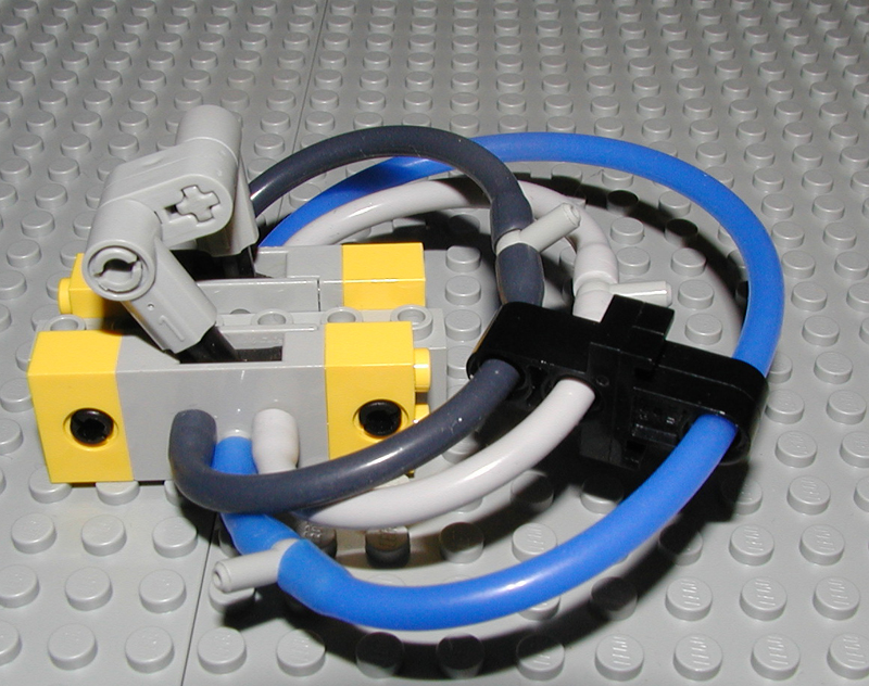
a switch without an OFF position. Doug Carlson and I worked on trying to
combine switches to eliminate the OFF position. Doug came up with this:
http://www.brickshelf.com/gallery/kclague/Computing/p6040061.jpg
When we tried to make make a piston control this off-less switch, and the switch
control the piston, the results were not very impressive. The piston did
oscillate, but at a very low amplitude. It was an unexpected outcome, but it
made sense once I thought about it.
My next effort to wrestle with the OFF position of a switch was to try to
mechanically combine rubber bands and some linkages to make a switch that hated
being in the off position. It utilized a concept hysteresis. Wikipedia defines
hysteresis as:
http://en.wikipedia.org/wiki/Hysteresis
In the case of pistons and switches hysteresis means not directly connecting the
piston and switch, but instead letting the piston move some, before it affects
ths switch.
In this single piston oscillator:
http://www.brickshelf.com/gallery/kclague/Oscillator/back.jpg
http://www.brickshelf.com/gallery/kclague/Oscillator/front.jpg
You can see that the rubber band tends to try to make the switch be thrown
either right or left. As the switch gets to the off position, the band
stretches, and tries to make the switch go back to either left or right. If,
when crossing the dead zone of the switch, there is even a little mechanical
momentum to get past center, the compression of the rubber band forces the
switch to the other end of the throw.
I used hysteresis in this so that the piston moved a ways before engaging the
switch, and then the switch would flip rapidly to the other extreme and reverse
the piston. This made for a very fast pneumatic oscillator. I was unable to
make it into an engine because the extents to which the piston expanded or
contracted was eratic.
After this, I stayed away from a piston controlling a switch that controlled
itself (the piston), and worked with multiple piston and switch sequencers.
A few days ago I realized that I could use this "piston turning itself off" idea
to my advantage, and that turning itself off is a good thing.
The trick is we need a way to get the piston going again. We need a way to
override the cut off pressure to the piston, so that we can force the piston to
one of its limits.
Enter the OR gate. Those of us in the know have talked a lot about logic gates
here on LUGNET. Most of the time we talk about AND gates, primarily because
they are the simples of all gates to make out of LEGO pneumatics. In this case
though, an OR gate is our friend.
Lets look at the world from the piston's point of view. The piston says "I'll
get pressure to my expand port if I'm contracted". It also says "I'll get
pressure to my contract port if I'm expanded". When the piston is at mid point,
the switch is turned off and the piston gets no pressure.
Let's change the piston's description of its expand port to say "I'll get
pressure to my expand port if I'm contracted, or if something else gives me
pressure". The most critical word in this new description is OR.
A few years ago Mark Tarrabain showed us his deceptively simple single piston,
single switch AND gate.
http://www.brickshelf.com/gallery/kclague/Computing/pswitch.jpg
It caught me off guard, because my designs for gates so far had been much more
complicated. I wondered what the smallest OR gate I could make. I figured out
how to make a single piston three switch OR gate.
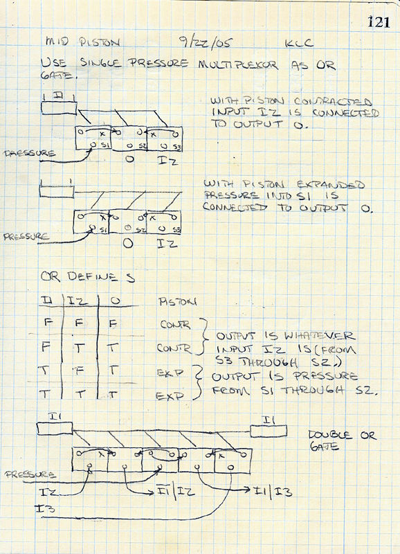
Here is a modern writeup of the OR gate I invented back then:
http://www.brickshelf.com/gallery/kclague/MidPiston/orgate.jpg
Much simpler than my original OR gate:
http://www.brickshelf.com/gallery/kclague/or-gate/or_schematic.jpg
So we can use an OR gate to get the piston moving again after it has stopped in
the dead zone.
I like to make walkers, so typically I make sequencers (circuits that go through
a small set of steps, and then repeate themselves). To use this mid-stop piston
concept in a walker, I needed a way to tell that the piston had stopped in the
middle.
I realized that to do this, I was going to need to use two switches, and my old
friend hysteresis. One switch helps us understand that we've traveled from
contracted to the middle, and the other switch lets us know that we've traveled
from expanded to the middle. They are set up such that if we've traveled from
contracted to the middle, and then expanded, then traveled from expanded to the
middle, both switches will let air pressure flow from their center ports, to one
of their left or right ports. By hooking these switches together serially we
know we're in the middle.
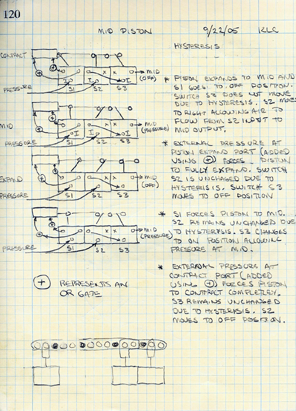
Here is a writeup from my LEGO idea logbook on combination of middle stop
switch, and the middle detect switches:
http://www.brickshelf.com/gallery/kclague/MidPiston/midpiston_descr.jpg
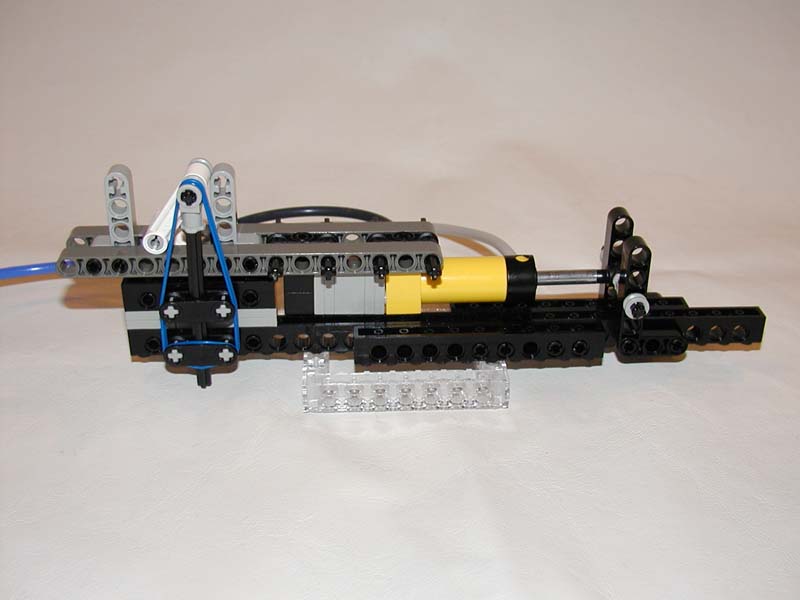
Here is a close up of an actual implementation of the mid-piston concept used in
a testbench I created. The switch on the left is actually unused. Notice the
two switches in the middle, with the #6 angle connectors. These are the
mid-piston detection switches. The #6 angle connectors, combined with the 1x15
liftarm, and the technic axle pins with half bushings, provide the hysteresis
mechanism.
To be sure that this mechanism actually worked, I created a little pneumatic
testbench. Logically I used three pistons (four actually, but two were combined
to act as one). One piston was wrappend in mid stop and mid detection switches,
the second was wrapped in OR gate switches, and the third was wrapped in AND
gates to glue them all together.
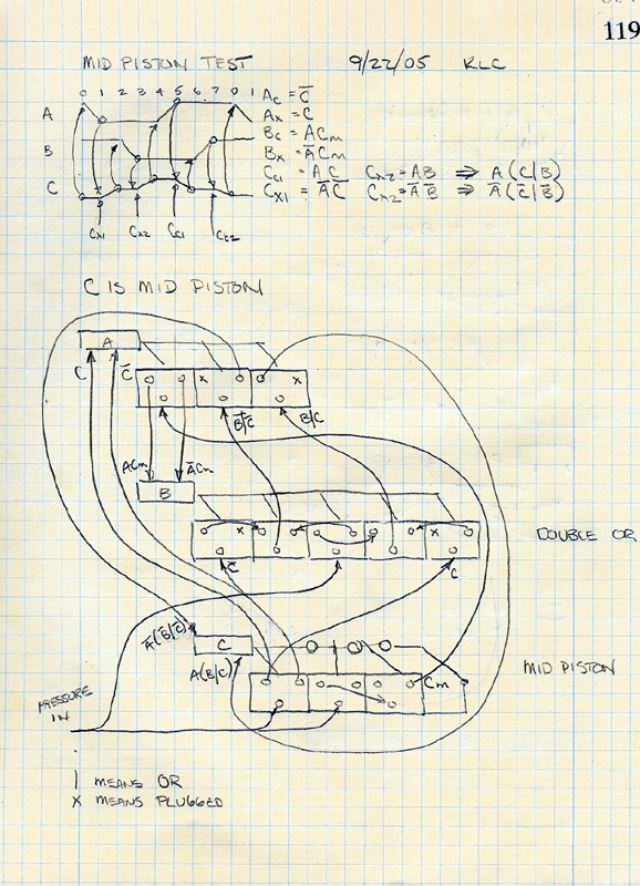
Here is a writeup from my idea logbook:
http://www.brickshelf.com/gallery/kclague/MidPiston/midtest_schematic.jpg
The timing diagram in the upper left hand corner describes what to expect:
time goes horizontally
pistons are listed vertically
up sloping lines means piston expanding
horizontal lines mean piston unchanged
down sloping lines mean piston contracting
The critical part of the timing diagram is piston C's waveform:
Notice the piston starts closed, opens to mid, expands fully, contracts to mid,
and finally contracts fully.
Overall the sequence is:
Piston A contracts.
Piston C expands to mid
Piston B contracts
Piston C expands fully
Piston A expands
Piston C contracts to mid
Piston B expands
Piston C contracts fully
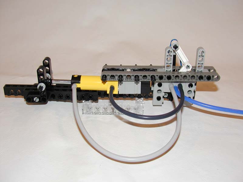
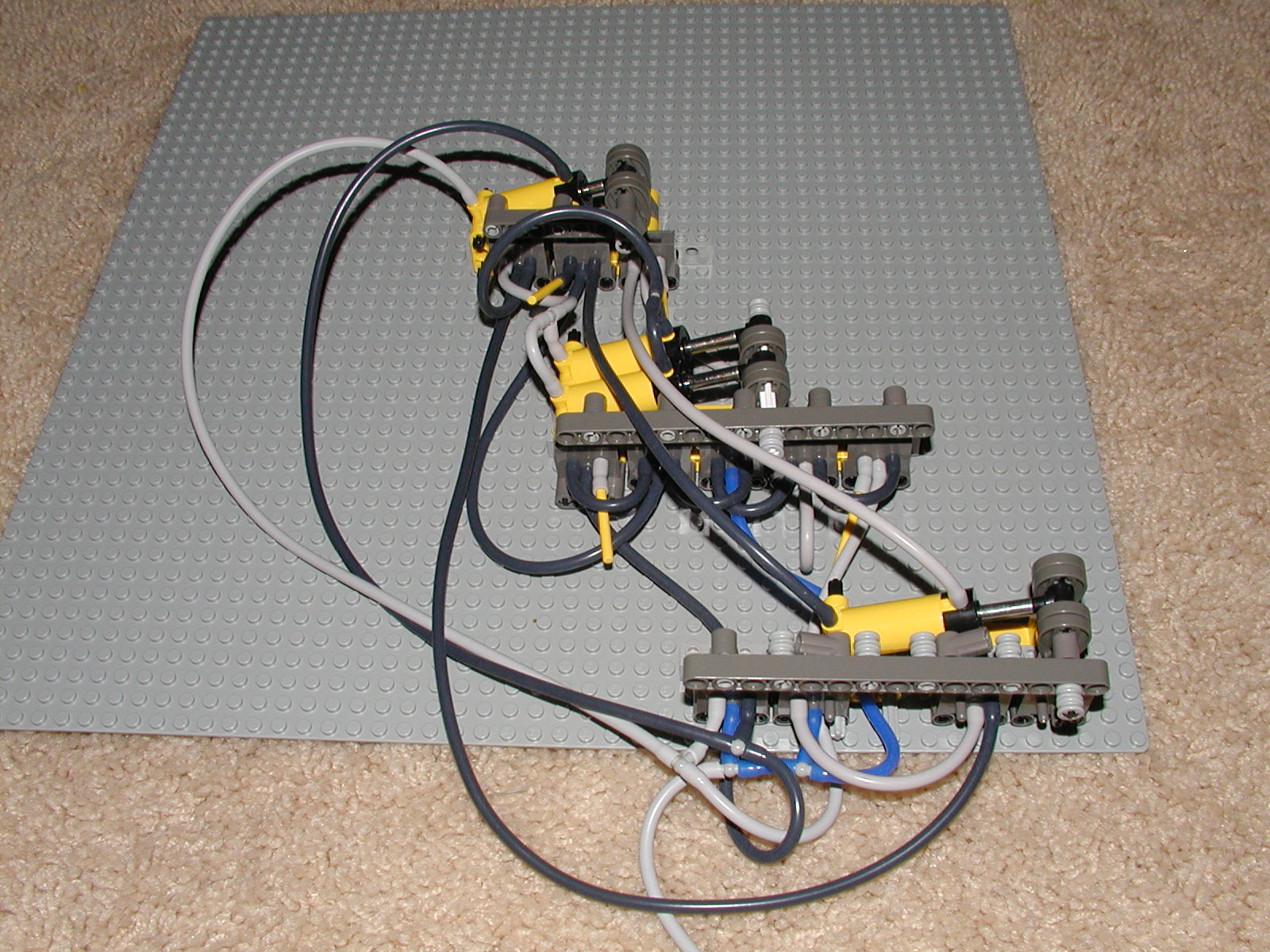
Here is a photograph of the actual circuit:
http://www.brickshelf.com/gallery/kclague/MidPiston/midpiston_test.jpg
Here is a movie of the circuit in action
http://www.kclague.net/midpiston/mid_piston.avi
Well, that's it! I'd love to hear from anyone who plays with this mid-piston
concept.
I already have a paper design for a six legged walker with three leg groups
using forward/mid/back leg sweeps (what a surprise!) It walks using a 9 step
sequence. It only uses mid-stop on expansion, but not on contraction.
Please let me know what you think.
Kev
|
|
Message has 3 Replies:
20 Messages in This Thread:
  ") 
 

- Entire Thread on One Page:
- Nested:
All | Brief | Compact | Dots
Linear:
All | Brief | Compact
|
|
|
|