 | | | | | | |
| |

|
I’ve crossposted to .trains because this will be useful for those wanting to
run LDCC with an RCX 2.
Hi All,
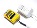
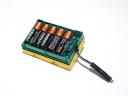
I’ve posted some photos on Brickshelf of an external power supply for the RCX 2.
The nice part about the design is that program memory is retained when external
power is removed. The other nice thing is that no mods are necessary to the RCX
(though if you want the battery cover to fit snugly, you may need to put a small
notch in the cover for the power cable to exit). The power cable is easily
removed when you want to convert back to battery operation.
Here’s a peek at the schematic:
For construction details, please see the notes.txt file and other photos in my
Brickshelf folder.
For trainheads interested in using this with LDCC: As an experiment, by
temporarily shorting one or two of the diodes (on the 12V path) with a small
piece of wire, you can get a higher track voltage. I felt safe trying this out
because the nominal voltage rating for the RCX H-bridges is 12V (max is 16V),
other analog components should be able to handle an extra volt or two, and the
CPU and RAM are supplied by a 5V regulator. Anyways, with the higher track
voltage the locomotives were much zippier, however, I’ve only tested this for a
little while so proceed with caution if you’d like to try this out yourself.
Mark
| | | | | | | | | | | | | | | |
"Mark Riley" <markril@hotmail.com> wrote:
> Hi All,
>
> I've posted some photos on Brickshelf of an external power supply for the RCX 2.
On a marginally related note, does someone out there have the
equipment to accurately test the output voltage of some typical dc
power supplies like the one used for this external ps? I tested every
ps I could find in my house (probably 20 or more) and *none* of them
put out the stated voltage. A typical 9v was putting out somewhere
between 12 and 15. This seemed to be a typical overvoltage percentage
(~50%). If someone else could check a few, it might provide some
useful information (I may not have a clue when testing).
If someone could test a genuine LEGO PS, that would be *really*
useful.
Thanks.
-Jon Gilchrist
| | | | | | | | | | | | | | | | | | | | | | |
| |
|
Jon Gilchrist wrote:
> "Mark Riley" <markril@hotmail.com> wrote:
>
> > Hi All,
> >
> > I've posted some photos on Brickshelf of an external power supply for the
> > RCX 2.
>
> On a marginally related note, does someone out there have the
> equipment to accurately test the output voltage of some typical dc
> power supplies like the one used for this external ps? I tested every
> ps I could find in my house (probably 20 or more) and *none* of them
> put out the stated voltage. A typical 9v was putting out somewhere
> between 12 and 15. This seemed to be a typical overvoltage percentage
> (~50%). If someone else could check a few, it might provide some
> useful information (I may not have a clue when testing).
>
> If someone could test a genuine LEGO PS, that would be *really*
> useful.
>
> Thanks.
>
> -Jon Gilchrist
You need to check the voltage while the PS is under load. Pretty much every
power supply puts out more when the load is low or nothing. Has to do with
loads of factors, but mostly quality of the PS (and (thus) internal
resistance of the PS) Just have it run a motor or several lights and then
measure the voltage again, should be a lot more within spec.
--
Jan-Albert van Ree | http://www.vanree.net/brickpiles/
Brick Piles | Santa Fe B-unit
| | | | | | | | | | | | | | | | | | | | | | |
On Wednesday 15 September 2004 19:20, Jon Gilchrist wrote:
> I tested every
> ps I could find in my house (probably 20 or more) and *none* of them
> put out the stated voltage. A typical 9v was putting out somewhere
> between 12 and 15.
It is nearly impossible to build a power supply that puts out the rated
voltage when there is no load. Most will put out too high a voltage (like
you have seen), some just shut down.
To meassure the voltage of a PS, shorten it with a 1000 Ohm resistor or
something like that and meassure the voltage at the resistor.
Ulrich
--
PGP key ID: 0xDF6FC4FA
"A mouse is a device used to select the xterm you want to type in."
Author unknown
| | | | | | | | | | | | | | | | | | | | | | | |
| |
|
Ulrich Schweitzer wrote:
> On Wednesday 15 September 2004 19:20, Jon Gilchrist wrote:
>
>
>
> > I tested every
> > ps I could find in my house (probably 20 or more) and *none* of them
> > put out the stated voltage. A typical 9v was putting out somewhere
> > between 12 and 15.
> >
> >
>
> It is nearly impossible to build a power supply that puts out the rated
> voltage when there is no load.
Not nearly impossible. It just requires a little more intelligence be
put into the power supply. All the regulated power supplies my company
produces contain a circuit called a down programmer. This circuits job
is to discharge the filter capacitors and maintain the rated voltage
under no-load conditions. It's essentially a fet or transistor run as a
load across the output, but to the user, the output of our supplies is
very, very stable. I'm pretty sure that if you found a good quality
wall wart (oxymoron? Is there such a beast?) it would contain a similar
circuit. Otherwise, just cheat and use a power resistor selected to
draw about 10% of the power supplies rated current. This should provide
decent load regulation at the expense of efficiency.
Rob
> Most will put out too high a voltage (like
> you have seen), some just shut down.
> To meassure the voltage of a PS, shorten it with a 1000 Ohm resistor or
> something like that and meassure the voltage at the resistor.
>
> Ulrich
>
>
| | | | | | | | | | | | | | | | | | | | | | | |
| |
|
On Thursday 16 September 2004 03:13, Rob Syvertsen wrote:
> Not nearly impossible. It just requires a little more intelligence be
> put into the power supply.
Sure it can be done, but it is very uncommon. I seriously doubt that any
wall-wart (even very good ones) do it. I have a very high quality
wall-wart. It puts out 2A at 3 to 24V, is very stable at the whole range
from very little to full load and even on sharp load changes. But at no
load the voltage is still about 15% above the rated voltage.
> All the regulated power supplies my company
> produces contain a circuit called a down programmer. This circuits job
> is to discharge the filter capacitors and maintain the rated voltage
> under no-load conditions. It's essentially a fet or transistor run as
> a load across the output,
I guess those are special purpose power supplies that for some reason need
this feature, aren't they? Also they will draw a lot more current at no
load than a power supply without this down programmer.
The thing is that in almost all cases the higher voltage without load is
simply no problem. It is a good idea to connect the PS to your gadget
before plugging it in anyways, so it will have a load from the very
beginning.
Ulrich
--
PGP key ID: 0xDF6FC4FA
"A mouse is a device used to select the xterm you want to type in."
Author unknown
| | | | | | | | | | | | | | | | | | |
| |
For trainheads interested in using this with LDCC: As an experiment, by
temporarily shorting one or two of the diodes (on the 12V path) with a small
piece of wire, you can get a higher track voltage. I felt safe trying this
out because the nominal voltage rating for the RCX H-bridges is 12V (max is
16V), other analog components should be able to handle an extra volt or two,
and the CPU and RAM are supplied by a 5V regulator. Anyways, with the higher
track voltage the locomotives were much zippier, however, I’ve only tested
this for a little while so proceed with caution if you’d like to try this out
yourself.
|
Indeed, the input capacitor of the RCX is rated 10V, so I would not do that for
a too long time. This 1000µF capacitor, used to keep memory during battery
exchange, is directly connected to RCX board supply input.
By the way, this capacitor is also great to zap the input fuse of the RCX (a
1.5A fast blow SMD fuse): if you power the RCX then accidentally make a dead
short across power terminals, it will discharge through the fuse and blow it...
Philo
| | | | | | | | | | | | | | | | | | | | |
In lugnet.robotics, Philippe Hurbain wrote:
| |
| |
For trainheads interested in using this with LDCC: As an experiment, by
temporarily shorting one or two of the diodes (on the 12V path) with a small
piece of wire, you can get a higher track voltage. I felt safe trying this
out because the nominal voltage rating for the RCX H-bridges is 12V (max is
16V), other analog components should be able to handle an extra volt or two,
and the CPU and RAM are supplied by a 5V regulator. Anyways, with the
higher track voltage the locomotives were much zippier, however, I’ve only
tested this for a little while so proceed with caution if you’d like to try
this out yourself.
|
Indeed, the input capacitor of the RCX is rated 10V, so I would not do that
for a too long time. This 1000µF capacitor, used to keep memory during
battery exchange, is directly connected to RCX board supply input.
|
Thanks for pointing that out, Philo. I think I’ll stick to the non-hopped up
version! :-)
| |
By the way, this capacitor is also great to zap the input fuse of the RCX (a
1.5A fast blow SMD fuse): if you power the RCX then accidentally make a dead
short across power terminals, it will discharge through the fuse and blow
it...
|
Hopefully you didn’t find this out the hard way...
Mark
| | | | | | | | | | | | | | | | | | | | | | |
| |
| |
By the way, this capacitor is also great to zap the input fuse of the RCX (a
1.5A fast blow SMD fuse): if you power the RCX then accidentally make a dead
short across power terminals, it will discharge through the fuse and blow
it...
|
Hopefully you didn’t find this out the hard way...
|
A friend did the mistake for me... but I had to repair a few of his RCXs! The
connector he used to plug an external supply was prone to be shorted (on RCX
side) when he unplugged it. It was only several fuses later that we understood
the problem!!!
Philo
| | | | | | | | | | | | | | | | | |
In lugnet.robotics, Mark Riley wrote:
| |
I’ve crossposted to .trains because this will be useful for those wanting to
run LDCC with an RCX 2.
Hi All,
...
For trainheads interested in using this with LDCC: As an experiment, by
temporarily shorting one or two of the diodes (on the 12V path) with a small
piece of wire, you can get a higher track voltage. I felt safe trying this
out because the nominal voltage rating for the RCX H-bridges is 12V (max is
16V), other analog components should be able to handle an extra volt or two,
and the CPU and RAM are supplied by a 5V regulator. Anyways, with the higher
track voltage the locomotives were much zippier, however, I’ve only tested
this for a little while so proceed with caution if you’d like to try this out
yourself.
Mark
|
On a closely related topic, here’s a circuit diagram for an RCX output booster.
Put one of these on each RCX output that you want to use to drive a train or a
more powerful motor (RCC motor?)
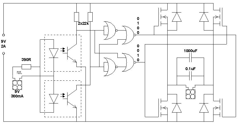
The circuit will control a higher power device with RCX variable speed control.
The input from the RCX is opto-isolated. This keeps the RCX output current low
and prevents any high power getting back to the RCX and damaging it. I’ve shown
9V 2A as the high power supply, since that’s what I intend to use for my trains,
but you should be able to use any supply if you get components of the right
ratings. The NOR gates are CMOS-compatible, so they’re limited to 15 Volts, but
you can always drop extra volts with diodes.
The large capacitor on the output is to turn the PWM of the RCX into smoother
power for the train motors. Remove it if you’re using LDCC as you don’t want to
smooth out the control signals.
My Pendolino, with four train motors, pulls 1 Amp at 7-8 Volts, so you can run
at least 10 train motors with a 3 Amp power supply with this circuit, making it
ideal for those triple headers with two helpers in the middle!
Connect the input to an RCX output and the output to one or more feed wires
(more for higher current). Connect a regulated 9V PSU to the power input. I’ll
use a dual 30V 3A supply (set to 9V) for two circuits driving two tracks. You
should be able to use a higher voltage for LDCC.
The output of this circuit will not float, since the protection diodes will
short the motor overrun through the power supply. Apart from that, the output
should be a high power version of the input.
Using MOSFETS means that there will be a small voltage drop that is proportional
to the current drawn. This helps prevent thermal runaway but means that for
high current applications you should experiment to find the best supply voltage.
I suggest using MOSFETs with an ON resistance of 10 milliohms or so, in a TO220
package since they’re easier to mount than a TO3. It might be convenient to
attach all four MOSFETs to a piece of aluminium via mica washers.
N.B. This circuit is a prototype and has not been tested, so I cannot accept any
responsibility for accidents or damage to anything you connect to it!
I intend to get some components and test it as soon as time permits. It should
mean I can control train speed with the RCX remote control - useful at
exhibitions!
Mark
| | | | | | |