| |
If you are a part author, I’d appreciate it if you read this post. I know it’s
long, but it needs to be in order to correctly describe the issue.
When looking at one one of the parts in the inaugural Part of the Month contest
in LDView (on my work machine that has an ATI video card), I noticed some dots
floating along some of the seams along the underside. After looking at the file
in wireframe, I came to the conclusion that these dots were caused by
T-junctions in the mesh. T-junctions are something that show up a lot in part
files, and it’s my opinion that an effort should be made to stop having them.
However, getting rid of them usually requires the addition of one extra polygon
(triangle or quad) per T-junction, and this is at odds with the general goal in
part files to use as few polygons as possible.
Since most people probably have no idea what I mean when I say T-junction (to be
honest, I’m not even sure that’s the correct technical term), I need to describe
both what a T-junction is, and why I think it’s bad to have them.
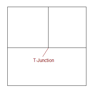
Simply put, a T-junction is a spot where two polygons meet along the edge of
another polygon, like so:
If these occur in a random location along a diagonal edge, it’s often the case
that the precise coordinates of the junction cannot be put into the DAT file.
Many people would agree that that would be bad. However, when they occur at
precise coordinates, it’s tempting to say that there’s nothing wrong with them,
since there shouldn’t be any round-off problems. Unfortunately, when you go to
arbitrary 3D views, this turns out not to be the case.
It turns out that a 3D rendering engine can only guarantee that a closed polygon
mesh is tight (no visible gaps) if the mesh does not contain any T-junctions.
The reason for this is that once you start rotating things in 3D, the precise
coordinates stop being precise. The following illustrates this problem:
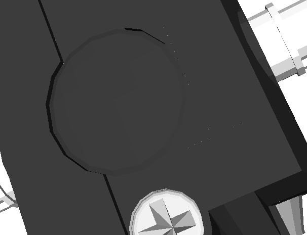
Notice the white dots. If you view the file in wireframe, you’ll see that these
dots occur along the seams between polygons. Please note that the actual
coordinates of all the points in the file are fine (as far as I know; I haven’t
checked, but I believe Mike). The dots are there because from that point of
view, the edges are diagonal, and diagonal edges require rounding. Essentially,
the rounding cannot be guaranteed to be the same on the polygons along the edge
if those polygons don’t share common end-points on both ends.
This may be difficult to understand. Hopefully the following will illustrate
the point:


The above images were done in Microsoft Paint (then blown up by 800%), with two
sets of lines that are designed to be right next to each other. The image on
the left represents the T-Junction case. The one on the right represents the
case without a T-junction. As you can see, there are gaps in the image on the
left. This isn’t quite the same as T-junctions in a part file, since the above
sets of lines were drawn with 1 pixel difference. However, since 3D renderers
are representing adjoining polygons with an infinitely thin edge between them,
it actually works out to a very similar problem. (Note that the red line in the
left image was actually drawn starting at the bottom-most green pixel, and the
green line was then drawn with the same end-point.)
Now, having said all this, I’ll mention that the dots aren’t visible with this
file on my nVidia video card at home. I have verified that the dots show up in
other files with T-junctions. Note that I disabled primitive substitution and
curve smoothing in LDView to make absolutely sure that LDView was only
displaying the actual geometry from the file.
I don’t know if the problem shows up in POV-Ray renderings. I did some quick
checks and didn’t see the problem, but that doesn’t prove that the problem won’t
show there. It just proves that POV-Ray at the very least seems to be more
resistant than LDView. However, I would like to stress that the dots are NOT
due to a bug in LDView. They aren’t something I have any control over (short of
splitting polygons when I load the part, and I’m not going to do that).
So, what do you as part authors think? Should T-junctions be avoided in order
to avoid the rendering errors that they can introduce, or should part authors
continue to strive to make parts with the fewest number of polygons possible?
--Travis
|
|
| |
In lugnet.cad.dat.parts, Travis Cobbs wrote:
| |
So, what do you as part authors think? Should T-junctions be avoided in
order to avoid the rendering errors that they can introduce, or should part
authors continue to strive to make parts with the fewest number of polygons
possible?
|
I try to minimise file size whenever possible myself and have nothing against T
juctions. While the gaps can be annoying I feel that they are a fault of the
rendering program rather than the parts.
|
|
| |
| |
So, what do you as part authors think? Should T-junctions be avoided in
order to avoid the rendering errors that they can introduce, or should part
authors continue to strive to make parts with the fewest number of polygons
possible?
--Travis
|
It’s possible that by setting up meshes POVray can largely avoid the problem as
it rotates points and then joins them. My opinion is that Part Authors should
stick to keeping the polygon count down rather than jumping through hoops to try
to avoid a problem which I suspect is fairly rare and not that important (it’s
only likely to be a problem at high-zoom).
Tim
Tim
|
|
| |
In lugnet.cad.dat.parts, Travis Cobbs wrote:
| |
So, what do you as part authors think? Should T-junctions be avoided in
order to avoid the rendering errors that they can introduce, or should part
authors continue to strive to make parts with the fewest number of polygons
possible?
|
in all the parts I’ve made so far there is just one with a t-junction:

(if I remember correctly it’s where the two red quads are surrounded by the
white border)
but it is forgiveable I think, as it was one of the first parts I’ve ever
authored. I have thought about many time to fix it just because of that
junction but since noone ever complained I stood silent. anyway, I consider
T-junk bad style, especially when used in combination with primitives. I do
not
care much about the number of polygons - which in my case is easy as I’m
always going for too much detail right from the start which ends in fat,
obese,
high calorie parts ... in no way healthy for your memory ;-)
w.
|
|
| |
In lugnet.cad.dat.parts, Travis Cobbs wrote:
| |
So, what do you as part authors think? Should T-junctions be avoided in
order to avoid the rendering errors that they can introduce, or should part
authors continue to strive to make parts with the fewest number of polygons
possible?
|
This is a really old issue. I think the previous consensus was that
T-Junctions are bad. Look at
the bottom of the message for the comments on T-Junctions.
Actually this is such an old issue, I could swear there was an ASCII art
illustration of the problem. But I can’t seem to find that anywhere now.
Have fun,
Don
|
|
| |
In lugnet.cad.dat.parts, Timothy Gould wrote:
| |
It’s possible that by setting up meshes POVray can largely avoid the problem
as it rotates points and then joins them. My opinion is that Part Authors
should stick to keeping the polygon count down rather than jumping through
hoops to try to avoid a problem which I suspect is fairly rare and not that
important (it’s only likely to be a problem at high-zoom).
|
It’s not really constrained to high zoom. If you have a 1% chance of any given
pixel along any given T-junction boundary edge resulting in a hole, then you’ll
have the roughly the same number of holes at any zoom level, since in general
the only reason to be zoomed further out is because there are more parts. It’s
true that the holes will be more randomly scattered (instead of showing up in
lines like my example), but they will still be present in roughly equal
quantities. Note also that they tend to be more obvious when rotating a part,
as their random nature causes them to pop in and out of existence, attracting
the eye to their presense.
And even if POV-Ray doesn’t suffer from the problem (which I still don’t know
one way or another), the relatively small number of additional polygons are
likely to have a minimal impact on the performance of POV-Ray. I’d say that
they’re unlikely to have a significant impact of the performance of realtime
viewers also, but since it can provide a noticeable improvement in realtime
viewers, I think it’s more helpful there.
--Travis
|
|
| |
In lugnet.cad.dat.parts, Willy Tschager wrote:
| |
in all the parts I’ve made so far there is just one with a t-junction:
(if I remember correctly it’s where the two red quads are surrounded by the
white border)
|
There are T-junctions there, but the ones that produce the most visible dots are
between the white stripe and the moon. Both of those colors are light, so the
dark background showing through is much higher contrast, which makes the dots
much more visible.
--Travis
|
|
| |
In lugnet.cad.dat.parts, Don Heyse wrote:
| |
This is a really old issue. I think the previous consensus was that
T-Junctions are bad. Look at
the bottom of the message for the comments on T-Junctions.
|
Much as I’d like to agree on this, I don’t think the fact that nobody posted
back then disagreeing with my statement really counts as consensus. I pointed
out the problem, but didn’t ask for opinions on whether parts should be modeled
that way.
Also, it’s kind of obvious that you and I would be biased on this issue. When
people complain that LDView or ldglite aren’t working right, all we can do right
now is say, “Too bad. There’s nothing I can do to fix it.” If there were an
official policy saying that T-junctions are bad, we could say, “The part needs
to be updated.”
| |
Actually this is such an old issue, I could swear there was an ASCII art
illustration of the problem. But I can’t seem to find that anywhere now.
|
That wouldn’t surprise me. Funny how things change.
--Travis
|
|
| |
--snip--
| |
And even if POV-Ray doesn’t suffer from the problem (which I still don’t know
one way or another), the relatively small number of additional polygons are
likely to have a minimal impact on the performance of POV-Ray. I’d say that
they’re unlikely to have a significant impact of the performance of realtime
viewers also, but since it can provide a noticeable improvement in realtime
viewers, I think it’s more helpful there.
--Travis
|
Just to be clear it’s not the render time I’m worried about... it’s the
authoring time.
Tim
|
|
| |
In lugnet.cad.dat.parts, Travis Cobbs wrote:
| |
In lugnet.cad.dat.parts, Don Heyse wrote:
| |
This is a really old issue. I think the previous consensus was that
T-Junctions are bad. Look at
the bottom of the message for the comments on T-Junctions.
|
Much as I’d like to agree on this, I don’t think the fact that nobody posted
back then disagreeing with my statement really counts as consensus. I
pointed out the problem, but didn’t ask for opinions on whether parts should
be modeled that way.
Also, it’s kind of obvious that you and I would be biased on this issue.
When people complain that LDView or ldglite aren’t working right, all we can
do right now is say, “Too bad. There’s nothing I can do to fix it.” If
there were an official policy saying that T-junctions are bad, we could say,
“The part needs to be updated.”
| |
Actually this is such an old issue, I could swear there was an ASCII art
illustration of the problem. But I can’t seem to find that anywhere now.
|
That wouldn’t surprise me. Funny how things change.
|
Heh, I think I found the ASCII art.
I coulda sworn it made it into a FAQ somewhere though. Oh well.
Have fun,
Don
|
|
| |
In lugnet.cad.dat.parts, Travis Cobbs wrote:
| |
Also, it’s kind of obvious that you and I would be biased on this issue.
When people complain that LDView or ldglite aren’t working right, all we can
do right now is say, “Too bad. There’s nothing I can do to fix it.” If
there were an official policy saying that T-junctions are bad, we could say,
“The part needs to be updated.”
|
T-junctions are a quality issue in part files. I don’t think they should be
strictly forbidden (that is, having T-junctions is not a reason to hold a part
file from official release). Generally, I wouldn’t even say that a part with
T-junctions needs a “(Needs Work)” tag. But I will encourage part authors to
avoid T-junctions. It is worth having a few more polygons to avoid the
rendering artifacts.
Sometimes, T-junctions can be avoided without any extra polygons -- it’s a
matter of knowing better ways to lay out polygons to cover a surface.
Steve
|
|
| |
In lugnet.cad.dat.parts, Steve Bliss wrote:
| |
T-junctions are a quality issue in part files. I don’t think they should be
strictly forbidden (that is, having T-junctions is not a reason to hold a
part file from official release). Generally, I wouldn’t even say that a part
with T-junctions needs a “(Needs Work)” tag. But I will encourage part
authors to avoid T-junctions. It is worth having a few more polygons to
avoid the rendering artifacts.
|
Sounds reasonable to me.
Any chance a T-junctions FAQ could be created on the parts tracker reference
page, and the above could make it into a policy statement in the parts review
FAQ? Most of my original post here could be used as the FAQ, but the tone is
perhaps too negative if we’re saying that they’re OK to have, but discouraged.
--Travis
|
|
| |
In lugnet.cad.dat.parts, Mark Kennedy wrote:
| |
In lugnet.cad.dat.parts, Travis Cobbs wrote:
| |
So, what do you as part authors think? Should T-junctions be avoided in
order to avoid the rendering errors that they can introduce, or should part
authors continue to strive to make parts with the fewest number of polygons
possible?
|
I try to minimise file size whenever possible myself and have nothing against
T juctions. While the gaps can be annoying I feel that they are a fault of
the rendering program rather than the parts.
|
I’d really appreciate it if you didn’t blame it on the rendering programs.
There’s really nothing that they can do to fix the problem. I can understand
why you might feel that they are at fault, but it really isn’t true. As such,
you might want to reconsider your position. (You might not, and that’s
perfectly valid, but if you don’t, hopefully you will at least acknowledge that
the renderers aren’t to blame for the artifacts; the T-junctions in the part
files are to blame.)
--Travis
|
|
| |
In lugnet.cad.dat.parts, Travis Cobbs wrote:
| |
In lugnet.cad.dat.parts, Mark Kennedy wrote:
| |
In lugnet.cad.dat.parts, Travis Cobbs wrote:
| |
So, what do you as part authors think? Should T-junctions be avoided in
order to avoid the rendering errors that they can introduce, or should part
authors continue to strive to make parts with the fewest number of polygons
possible?
|
I try to minimise file size whenever possible myself and have nothing
against T juctions. While the gaps can be annoying I feel that they are a
fault of the rendering program rather than the parts.
|
I’d really appreciate it if you didn’t blame it on the rendering programs.
There’s really nothing that they can do to fix the problem. I can understand
why you might feel that they are at fault, but it really isn’t true. As
such, you might want to reconsider your position. (You might not, and that’s
perfectly valid, but if you don’t, hopefully you will at least acknowledge
that the renderers aren’t to blame for the artifacts; the T-junctions in the
part files are to blame.)
--Travis
|
Arguably it’s probably the algorithms and/or numerical proccessing that are at
fault. Certainly when you design scientific code algorithms they should usually
be created in such a way that it minimises numerical error. Of course I don’t
expect the authors of viewing software to redesign/rewrite/overwrite the inbuilt
alogrithms of the GPUs or emulators but there is no such thing as an intractable
problem [1]
Tim
[1] Well there probably are but they’d be highly obscure creations designed
purely to be intractable.
|
|
| |
In lugnet.cad.dat.parts, Travis Cobbs wrote:
| |
In lugnet.cad.dat.parts, Mark Kennedy wrote:
| |
In lugnet.cad.dat.parts, Travis Cobbs wrote:
| |
So, what do you as part authors think? Should T-junctions be avoided
in order to avoid the rendering errors that they can introduce, or
should part authors continue to strive to make parts with the fewest
number of polygons possible?
|
I try to minimise file size whenever possible myself and have nothing
against T juctions. While the gaps can be annoying I feel that they are a
fault of the rendering program rather than the parts.
|
I’d really appreciate it if you didn’t blame it on the rendering programs.
There’s really nothing that they can do to fix the problem. I can
understand why you might feel that they are at fault, but it really
isn’t true.
|
Well... Technically it is true. The rendering program ought to be
able to scan all the points in each part and look for intersections
with every edge in the part. Then break up the offensive T-joins
automagically and render it perfectly. That’s only O(n^2) or so.
Blink of an eye on today’s processors.
Doesn’t ldview do this already? I’m sure txt2dat does. Try to be
a little more up to date, will ya? ;^)
Have fun,
Don
|
|
| |
In lugnet.cad.dat.parts, Don Heyse wrote:
| |
Well... Technically it is true. The rendering program ought to be
able to scan all the points in each part and look for intersections
with every edge in the part. Then break up the offensive T-joins
automagically and render it perfectly. That’s only O(n^2) or so.
Blink of an eye on today’s processors.
|
OK, I stand corrected. Technically a program can fix things a load time.
However, you might be surprised at how long it takes. It’s “only” O(n^2), but
each iteration is slow. You have to search the current line segment against
all other line segments in the part, and find any partial overlaps. And n in
this case is the total number of points in the entire part, not just the current
file, since it’s perfectly valid for things to blend across sub-part/primitive
boundaries (look at where the studs meet the main body of the 2x2 round brick).
| |
Doesn’t ldview do this already? I’m sure txt2dat does. Try to be
a little more up to date, will ya? ;^)
|
Assuming txt2dat does this, bear in mind that it doesn’t really have to be all
that fast, since it gets run once and the generated data then gets used as often
as needed. Mind you, I’m guessing that it would actually be reasonably fast,
but the total number of points isn’t likely to be all that large. Feed the
crater baseplate into the same algorithm, and it might take a noticeable amount
of time. Oh, and txt2dat can do it in 2D, which is both easier and faster than
in 3D.
Having said all that, I’d personally be surprised if txt2dat does it at all. It
knows where all the outline points are on the text; I’m assuming it just uses a
standard concave polygon tesselation algorithm for each character in the text,
and the same thing for the background quad (treating the text polygons as
holes).
And, if you want to see that these types of things can take enough time to be
noticeable, turn off primitive substitution in LDView, then load a big model
both with and without curve smoothing enabled. It will take longer with curve
smoothing enabled. Brad Hamilton’s cathedral model, for example, reloads in 5
seconds with curve smoothing disabled, and 13 seconds with curve smoothing
enabled. (With primitive substitution turned on, it takes 8 seconds with curve
smoothing enabled, because none of the studs have to be smoothed.) Granted,
that model has 5655 parts, which is a lot, but those timings are on a 3.8GHz P4.
The difference in load times is purely based on the algorithmic complexity of
the my curve smoothing algorithm (which I’m going to estimate will run faster
than this proposed algorithm, although I could be wrong about that).
--Travis
|
|
| |
In lugnet.cad.dat.parts, Don Heyse wrote:
| |
Well... Technically it is true. The rendering program ought to be
able to scan all the points in each part and look for intersections
with every edge in the part. Then break up the offensive T-joins
automagically and render it perfectly. That’s only O(n^2) or so.
Blink of an eye on today’s processors.
Doesn’t ldview do this already? I’m sure txt2dat does. Try to be
a little more up to date, will ya? ;^)
|
Well actually what txt2dat does is a slightly different problem - it has a few
simple closed loops and has to triangulate the complex polygons bounded by them
(it uses the excellent triangle
library to do that).
Renderers on the other hand would have to check every edge for intersections,
and perform rudimentary triangulation when an intersection is found. And only to
correct a small problem on a minimum of parts - that’s a fair bit of extra
processing for not much gain, when the problem COULD be corrected at the
source...
I do however agree that it should not be a requirement for parts, but rather a
suggestion for authors. Maybe it could also be a suggestion for renderer
authors, to provide the extra processing as a switchable option.
ROSCO
|
|
| |
In lugnet.cad.dat.parts, Timothy Gould wrote:
| |
there is no such thing as
an intractable problem
|
There is, however, such a thing as an impractical problem ;)
ROSCO
|
|
| |
In lugnet.cad.dat.parts, Travis Cobbs wrote:
| |
In lugnet.cad.dat.parts, Don Heyse wrote:
| |
Well... Technically it is true. The rendering program ought to be
able to scan all the points in each part and look for intersections
with every edge in the part. Then break up the offensive T-joins
automagically and render it perfectly. That’s only O(n^2) or so.
Blink of an eye on today’s processors.
|
OK, I stand corrected. Technically a program can fix things at load time.
However, you might be surprised at how long it takes. It’s “only” O(n^2),
but each iteration is slow. You have to search the current line segment
against all other line segments in the part, and find any partial overlaps.
And n in this case is the total number of points in the entire part, not
just the current file, since it’s perfectly valid for things to blend across
sub-part/primitive boundaries (look at where the studs meet the main body of
the 2x2 round brick).
| |
Doesn’t ldview do this already? I’m sure txt2dat does. Try to be
a little more up to date, will ya? ;^)
|
Assuming txt2dat does this, bear in mind that it doesn’t really have to be
all that fast, since it gets run once and the generated data then gets used
as often as needed....
|
blah, blah, blah, snip
Oops, I was trying to be all ironical in a geeky math sorta way. But
apparently I failed. Guess I shoulda used more winkies... Do people
still use winkies? Or have they gone obsolete like ASCII art?
Anyhow, sorry about that. Have fun,
Don
|
|
| |
In lugnet.cad.dat.parts, Ross Crawford wrote:
| |
In lugnet.cad.dat.parts, Timothy Gould wrote:
| |
there is no such thing as
an intractable problem
|
There is, however, such a thing as an impractical problem ;)
ROSCO
|
No there’s not. I’m a physicist... not an engineer ;)
Tim
|
|
| |
Something else to consider is that T junctions will often appear in model files
themselves between two parts as shown in this simple example.
0 Model exported from LeoCAD
0 Original name:
1 4 20.00 -24.00 30.00 1.00 0.00 0.00 0.00 1.00 0.00 0.00 0.00 1.00 3001.DAT
1 4 60.00 0.00 30.00 1.00 0.00 0.00 0.00 1.00 0.00 0.00 0.00 1.00 3001.DAT
1 4 -20.00 0.00 30.00 1.00 0.00 0.00 0.00 1.00 0.00 0.00 0.00 1.00 3001.DAT
0
|
|
| |
In lugnet.cad.dat.parts, Mark Kennedy wrote:
| |
Something else to consider is that T junctions will often appear in model
files themselves between two parts
|
Yes, that’s true, but in such cases there are generally lines separating the
polygons (parts), and people expect to see those in the render. The problem
we’re talking about here is artifacts showing up on the faces of individual
parts where people don’t expect them.
ROSCO
|
|
|