| |
Here are my drawings of the RCX sensor port and power supply circuits, complete
with measured voltages from inside the box. These are averages measured with a
DMM, not an indication of peak waveforms. I might use an oscilloscope later if
there’s a demand for it.
This is the sensor port circuit:
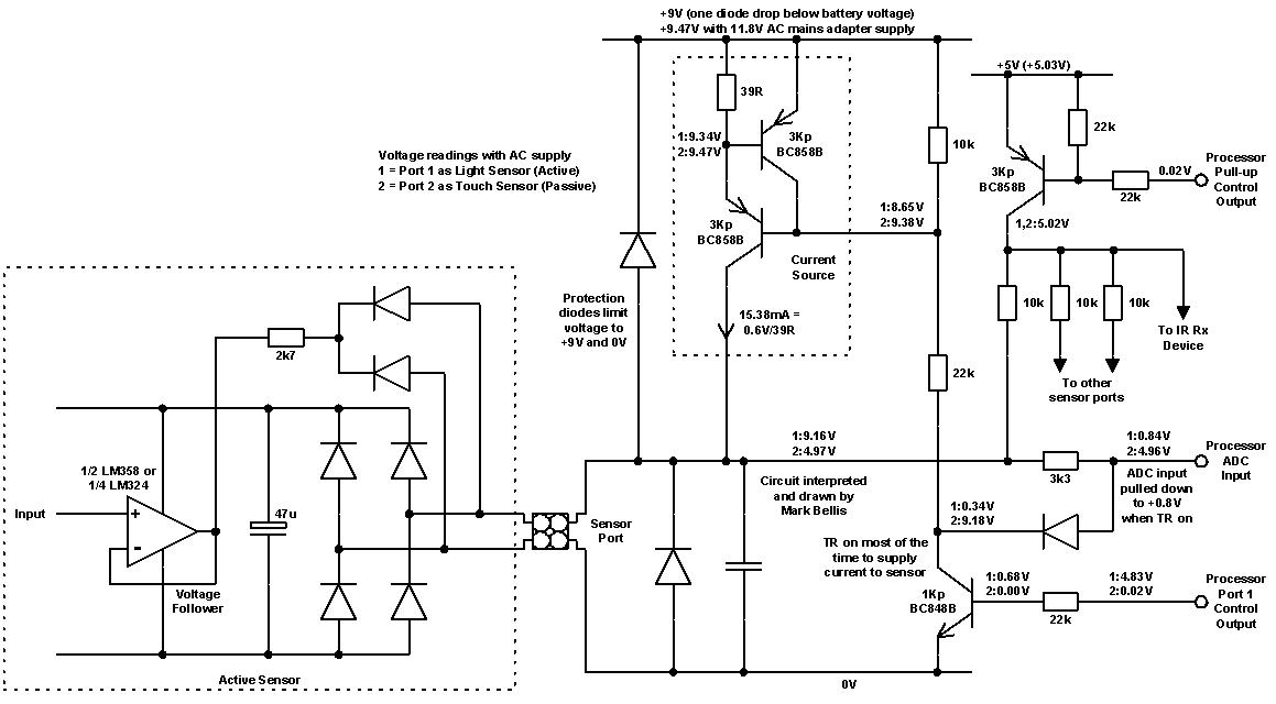
The readings for active and passive sensors basically differ by the fact that
the 15.38mA current source is only used for the active sensors.
All three sensor ports and the IR receiver are powered from the same transistor
pull-up to +5V. I think this transistor may implement a delay function when the
RCX is switched on, to make sure the processor is powered before any voltage
appears at its ADC ports, so as not to damage them.
The voltage at the port, to power active sensors, will vary depending on the
supply voltage (mains or battery) and the current drawn by the sensor. It is
over 9V with mains supply but may be as little as 7.6V with 9.0V batteries (one
diode drop in supply circuit, 0.6V for current source resistor plus 0.2V for
current source transistor C-E saturation). This will decrease further as the
batteries wear out. Therefore sensors should be made to work with voltages
between about 7V and 9.2V.
The bottom right diode prevents overvoltage at the ADC input, pulling it down to
0.8V when the current source is on.
This is the power supply circuit:
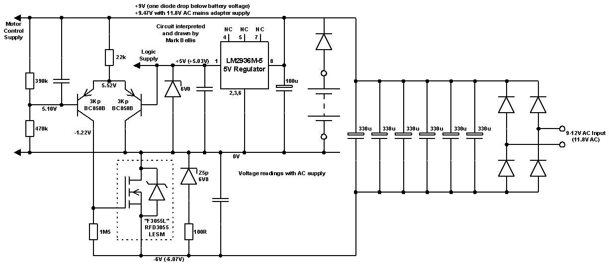
The 11.8V AC (from a 9V train adapter) is rectified to about 15.5V DC, smoothed
by the capacitors. Presumably 6 x 330uF was the best fit within the case for
the total capacitance required. The 5V regulator is used as a reference to set
the current through the 22k resistor, via the right hand 3Kp transistor. The
left hand 3Kp transistor receives a proportion of the 9V supply. This tells the
MOSFET how much voltage to drop in order to keep the 9V supply stable, dropping
about 6V with this AC supply. This will vary with other supply voltages. If
three motors were being powered, the 11.8V AC would drop towards 9V under load.
This would cause the 9V rail to drop, but the MOSFET compensates by dropping
less voltage itself, keeping the 9V supply stable.
I don’t think there is any switching in this supply, though that is what the
MOSFET is designed for.
The maximum MOSFET regulation is 6.8V, set by the zener diode, so the maximum
safe DC voltage is 9.5 + 6.8 = 16.3V, so the maximum AC input is (16.3 +
1.2)/1.414 = 12.4V AC, which is why the maximum says 12V on the case.
With a 9.0V AC input, the rectifier produces (9*1.414)-1.2 = 11.5V. Assuming
9.5V for the 9V DC supply, the MOSFET drops 2.0V.
PLMKWYT
Mark
|
|
1 Message in This Thread:

- Entire Thread on One Page:
- Nested:
All | Brief | Compact | Dots
Linear:
All | Brief | Compact
|
|
|
|
