 | | | | | |
In lugnet.parts.custom, Mark Bellis wrote:
| |
I wish TLC would make these parts. Seeing earlier discussions I think I’m
not alone! I’ve attempted 3rd angle projection drawings, showing top, side
and underside, despite not having a drawing package. Drawing these parts in
Paint is eyestrain city!
|
YIKES!
Well, OK, this is what I need for my students to model parts in AutoCAD! I tried
this one because it looked the easiest; I’ll do the others if there’s interest.
I don’t know if anyone else has mocked these up already..
It took me about 10 minutes, but mainly because I had to figure out how STL2DAT
worked (I usually use 3DWin, but it didn’t do such a great job). It looks OK in
MLCAD, but I know it’s pretty messy.. I guess good enough to throw a MOC
together for fun.
http://www.brickshelf.com/cgi-bin/gallery.cgi?f=115617
Darrell
| | | | | | | | | | | | | | |
In lugnet.parts.custom, Darrell Urbien wrote:
| |
In lugnet.parts.custom, Mark Bellis wrote:
| |
I wish TLC would make these parts. Seeing earlier discussions I think I’m
not alone! I’ve attempted 3rd angle projection drawings, showing top, side
and underside, despite not having a drawing package. Drawing these parts in
Paint is eyestrain city!
|
YIKES!
Well, OK, this is what I need for my students to model parts in AutoCAD! I
tried this one because it looked the easiest; I’ll do the others if there’s
interest. I don’t know if anyone else has mocked these up already..
It took me about 10 minutes, but mainly because I had to figure out how
STL2DAT worked (I usually use 3DWin, but it didn’t do such a great job). It
looks OK in MLCAD, but I know it’s pretty messy.. I guess good enough to
throw a MOC together for fun.
http://www.brickshelf.com/cgi-bin/gallery.cgi?f=115617
Darrell
|
Are you doing 3rd angle projection or 3D?
10 minutes is a lot less than it took me in Paint. I suppose once you’re
trained in AutoCAD, a lot of things are quick.
Could you post jpegs of the results?
I created bits like studs in the drawing and did a lot of copying and pasting.
getting them to line up well with a limited screen size was the main problem in
Paint. I suppose the CAD packages automatically line things up for you.
Mark
| | | | | | | | | | | | | | | | |
In lugnet.parts.custom, Mark Bellis wrote:
| |
Are you doing 3rd angle projection or 3D?
10 minutes is a lot less than it took me in Paint. I suppose once you’re
trained in AutoCAD, a lot of things are quick.
Could you post jpegs of the results?
|
Hi,
Yeah, I’m working in ACIS Solids, then exporting to STL, then from STL2DAT. I’ll
try to do a few more this weekend and post the results to the same folder.
Something to do between TO soundbytes, anyway.
Is the DAT file helpful at all, or do you just want the orthographic
views/renderings? The views and images are cake compared to futzing with
converting the 3D model to DAT!
Darrell
| | | | | | | | | | | | | | | | |
In lugnet.parts.custom, Darrell Urbien wrote:
| |
In lugnet.parts.custom, Mark Bellis wrote:
| |
Are you doing 3rd angle projection or 3D?
10 minutes is a lot less than it took me in Paint. I suppose once you’re
trained in AutoCAD, a lot of things are quick.
Could you post jpegs of the results?
|
Hi,
Yeah, I’m working in ACIS Solids, then exporting to STL, then from STL2DAT.
I’ll try to do a few more this weekend and post the results to the same
folder. Something to do between TO soundbytes, anyway.
Is the DAT file helpful at all, or do you just want the orthographic
views/renderings? The views and images are cake compared to futzing with
converting the 3D model to DAT!
Darrell
|
Please don’t go to a lot of trouble on my account!
It’s just that I usually post jpegs or bitmaps of things to my Brickshelf, since
anyone can view them without any special software. I’m not seriously into CAD!
If I had the facilities to actually make some of these parts, I might think more
seriously about CAD. I did download MLCAD, but have hardly used it yet due to
lack of time. If I did CAD I wouldn’t have time to build! You can see from my
Brickshelf that I major in trains and technic:
http://www.brickshelf.com/cgi-bin/gallery.cgi?m=mbellis My CAD expertise is
more developed in circuit diagrams (see technic mindstorms folder), but this is
2D and very quick in Visio, now that I’ve drawn a few component symbols.
If others want to make a library of wished-for parts, then CAD would be the way
to go. If the relationship with TLC’s parts design department could be
established, I’m not sure what format would be best for submission of designs.
I suggest some sort of universal engineering drawing, that could be converted to
whatever they use.
For now though, I suggest a format like jpeg or bitmap that everyone can see
without CAD software, so that we can maximise community involvement. Those with
CAD expertise can draw parts that others have thought of, as well as their own,
and we could make a collective submission to TLC. I’ve realised that I haven’t
time to do everything on my own, and that I need to work as part of a team in
the community with others who specialise in different skills.
If you can draw parts easily and post 3D or 3rd angle projection jpegs on
Brickshelf, these parts, which I have actually made, would be useful:
1. Axle peg with peg cut off, leaving axle and bezel. Start with this piece:
http://www.peeron.com/inv/parts/3749
These are so useful that I’ve made at least 50 of them! They go through a round
hole into an axle hole on another piece, allowing them to pivot in an 8mm wide
space. Great for valve gear on steam engines, supporting wheels alongside train
motors, and many other uses.
2. Peg with stud, with stud cut off, leaving peg and bezel. Start with this
piece: http://www.peeron.com/inv/parts/4274
Also useful for pivoting two 4mm wide pices with round holes in a tight space.
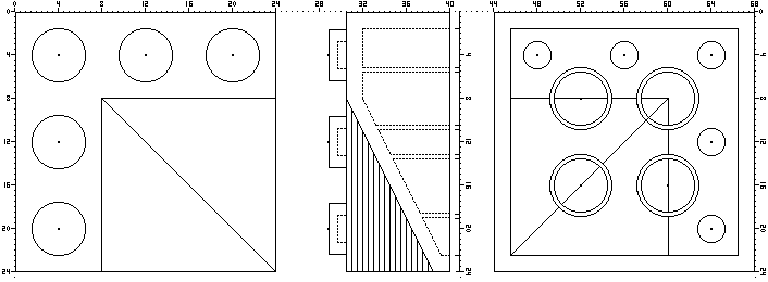
3. 24mm Pulley with all holes cut off except centre axle hole and one hole at 30
degrees from the axle alignment. Hold the pulley with the holes in rows of 2,
3, and 2. The off-centre hole to keep is one of the holes in a row of 2. The
result is a crank offest by 30 degrees, or 60 degrees if you reverse it. When
used with the centre on an offset of 1 stud on a 40-tooth cog or model team
wheel, the result is a 0.5 stud offset from the wheel centre with a 90 degree
lead or lag, for steam engine valve gear. Start with this piece:
http://www.peeron.com/inv/parts/4185
4. Steam engine expansion link. Start with this piece:
http://www.peeron.com/inv/parts/6632
Drill out one of the end axle holes to make it a round hole, then make the cut
hole and the centre hole into one slot, so that a peg could be in the hole and
slide along it.
5. 3L 4mm wide liftarm and 2L liftarm with one axle hole and one round hole. To
make them, start with this piece: http://www.peeron.com/inv/parts/2905
Cut the triangle into three, making one 3L liftarm with 3 round holes and two 2L
liftarms each with one axle hole and one round hole. Tidy up the edges to give
them rounded ends. To CAD them, start with the 3L liftarm, as 4. above. I used
the 2L liftarms in my Apache helicopter, to do cranks for the pitch control in a
small space. Both pieces have many uses!
6. Quarter bush. Cut this piece in half to make two 2mm-wide bushes:
http://www.peeron.com/inv/parts/4265c
Great for offsetting rotating things so that they don’t bind on each other.
Also for spacing axles in tight spaces, such as vertical axle pivot on
articulated train bogies. I keep making more of these!
These are parts that I would very much like TLC to make properly, since my
cutting and filing isn’t perfect! If you drew them I would put your name on the
drawings and post them in my Brickshelf folder of parts that I’ve made.
Mark
| | | | | | | | | | | | | | | | | |
In lugnet.parts.custom, Mark Bellis wrote:
| |
In lugnet.parts.custom, Darrell Urbien wrote:
| |
In lugnet.parts.custom, Mark Bellis wrote:
| |
Are you doing 3rd angle projection or 3D?
10 minutes is a lot less than it took me in Paint. I suppose once you’re
trained in AutoCAD, a lot of things are quick.
Could you post jpegs of the results?
|
Hi,
Yeah, I’m working in ACIS Solids, then exporting to STL, then from STL2DAT.
I’ll try to do a few more this weekend and post the results to the same
folder. Something to do between TO soundbytes, anyway.
Is the DAT file helpful at all, or do you just want the orthographic
views/renderings? The views and images are cake compared to futzing with
converting the 3D model to DAT!
Darrell
|
Please don’t go to a lot of trouble on my account!
It’s just that I usually post jpegs or bitmaps
|
Please consider not posting bitmaps. They are very space intensive and take a
long time to load. Instead use a lossless compressed format like .gif if you
can. In my view jpegs are not as good for things like line drawings, they are
better for continuous tone photos.
| |
of things to my Brickshelf,
since anyone can view them without any special software. I’m not seriously
into CAD!
If I had the facilities to actually make some of these parts, I might think
more seriously about CAD. I did download MLCAD, but have hardly used it yet
due to lack of time. If I did CAD I wouldn’t have time to build! You can
see from my Brickshelf that I major in trains and technic:
http://www.brickshelf.com/cgi-bin/gallery.cgi?m=mbellis My CAD expertise is
more developed in circuit diagrams (see technic mindstorms folder), but this
is 2D and very quick in Visio, now that I’ve drawn a few component symbols.
|
Would you consider sharing your Visio library occasionally? Just a zip would be
great. Visio is a great tool I think!
Thanks!
| | | | | | | | | | | | | | | | | | | | |
In lugnet.parts.custom, Larry Pieniazek wrote:
| |
In lugnet.parts.custom, Mark Bellis wrote:
| |
...
It’s just that I usually post jpegs or bitmaps
|
Please consider not posting bitmaps. They are very space intensive and take a
long time to load. Instead use a lossless compressed format like .gif if you
can. In my view jpegs are not as good for things like line drawings, they are
better for continuous tone photos.
|
I only use bitmaps when they are smaller than the equivalent jpeg - ie they are
monochrome ones. This was the case for the parts I’ve drawn so far. I’ve used
jpegs for colour pictures up to now.
I did a test with the 4x4 round plate drawing:
monochrome bitmap is 34KB
jpeg is 66KB
png is 63KB but loses definition
gif is 13KB
In this case the jpeg is larger than the bitmap, which is why I posted the
bitmap. I haven’t yet investigated GIFs or PNGs, so perhaps you could tell me:
Is GIF the standard highest compression, lowest loss format? If so, why doesn’t
everyone use them? I’ve seen animation in GIFs - how do you do that?
What are PNGs used for, since they lose definition?
Are GIFs or PNGs any more vulnerable to viruses than jpegs or bitmaps?
| |
| |
My CAD expertise is more developed in circuit diagrams
(see technic mindstorms folder), but this is 2D and very quick in
Visio, now that I’ve drawn a few component symbols.
|
Would you consider sharing your Visio library occasionally? Just a zip would
be great. Visio is a great tool I think!
Thanks!
|
I’m glad Visio is so quick, since I can draw some circuits in my 30 minute lunch
break, saving on needing Visio at home. I copy the drawing to Paint and save as
a jpeg, since Visio seems to have a problem with saving picture files. I only
use the internet at home, due to work policy. Posted pictures are still open to
doctoring, but give away a little less than the source files. Perhaps you would
like to develop your own style :-) Feel free to use a print of one of my
circuits as you design your component symbols though.
For a resistor I drew a 1x2 rectangle with no fill at 100% in Visio, then at
200% added leads the same length as the box to the centres of the ends of the
box. I then put a text box by the side for the value. I grouped the four items
and set the double-click action to “Open group in new window”, so that I can
copy the resistor and edit the resistance value rather than draw another one.
I did the same with capacitors and diodes, making them a similar size. I’ve
done other components as required, keeping the same proportions, but now have
transistors, op-amps, batteries, relay contacts, Lego 9V plugs and some logic
gates. Other components are just a box. I use a line with the end set to 10
(round blob) a lot, since every T-junction should have a blob. I keep one of
each component in a template file, which I copy to start a new diagram. When I
start a new one I just delete the components I know I won’t need. For posting
on Brickshelf I set the line weight to 9 so that the wires show up.
The results are here: http://www.brickshelf.com/cgi-bin/gallery.cgi?f=97964
Hmmm.. I think the FUT should be to lugnet.cad!
Mark
| | | | | | | | | | | | | | | | | | |
In lugnet.parts.custom, Mark Bellis wrote:
| |
Please don’t go to a lot of trouble on my account!
|
Hi,
No real “trouble” - I do this for a living. It’s the DAT conversion that’s
slightly fussy. If you’re not using MLCAD with your custom parts, I don’t know
if there’s much demand otherwise! So I may as well just skip that bit.
| |
If others want to make a library of wished-for parts, then CAD would be the
way to go. If the relationship with TLC’s parts design department could be
established, I’m not sure what format would be best for submission of
designs. I suggest some sort of universal engineering drawing, that could be
converted to whatever they use.
|
Somehow I don’t see TLG designers wanting or needing to see fan-created CAD
files. IF they were interested in the designs, they’d probably create all that
stuff on their own; all you’d need are renders/DAT files of your parts to convey
the idea to them. Heck, if it’s a good enough part idea you could sell it with a
sketch on a napkin..
All commercial CAD software can output to common image file formats. Modified
DAT files can be read in MLCAD or other viewers. IOW, I don’t think
standardization of the format is an issue.
| |
If you can draw parts easily and post 3D or 3rd angle projection jpegs on
Brickshelf, these parts, which I have actually made, would be useful:
|
Having said all that, sure, I can model your files and give you renders or ortho
views (again I don’t think detailed dimensions are really necessary). I’d
already modeled most of the parts you mention for a CAD class I teach.
However, is there any way you could post a picture of all the modded parts
you’ve actually made? Maybe even a before-after type thing? I’m having a hard
time understanding the mod to the pulley just from your words, and I know
nothing about trains so I don’t understand the context of its use.
Darrell
| | | | | | |