|
|
| |
In lugnet.technic, Jetro de Chateau wrote:
| |
In lugnet.technic, Mark Bellis wrote:
| |
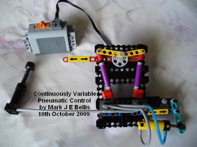
To celebrate, here are the pictures of my latest pneumatic system.
It allows the cylinder to be commanded to any position.
• not just the two ends
• not just two ends and one position in the middle
• yes, any variable position within its travel!
|
Thank you for sharing this. Next up: implementing this in an automated
system...
Jetro
|
Here’s a video tutorial that explains how it works:
http://www.youtube.com/profile?user=mbellisbrickmocs#p/u/0/9jv73J8-4Zw
The demonstration model is an automated system in itself. It is the inner loop
of a control system. The (optional) outer loop would use feedback from a driven
device to move the red beam, but not all applications need an outer loop. The
cylinder pictured can be the cylinder that drives the model function, or
parallel cylinders from the same hoses can do that. It could be most of the
system or a building block for a larger system. I like the fact that few enough
pneumatic elements are used that it should be accessible to more people.
I thought of a few applications for the system:
- Truck suspension including centre lift or tag axle (redistribute the force to
the non-lifting wheels)
- With higher feedback gain, a show car bouncy
suspension or monster truck jumping function.
- Anti-roll suspension, putting
more pressure to the outside wheels when cornering.
- Power steering (add an
axle across the system, to keep the wheels in sync with the steering wheel).
-
Robot leg force balancing or body weight distribution for a biped.
- NXT
precise control of pneumatics. The NXT motor with its shaft encoder can tell
the position of the red beam if driven by a worm and rack. Therefore the NXT
can know what the cylinder position set point is and can use open loop control
with a suitable delay for the actual cylinder position.
I have a few more ideas for multiple applications in one model, which I will
think about further. A smooth drive steam engine should be possible, varying
the pseudo-steam pressure and hence implementing a real steam loco reverser
speed control function. The levers in the demonstration model do a similar
thing to the valve gear in a steam engine, adding together the piston position
and the reverser position. The gains of input, dither and feedback would be
adjusted for each application.
Hope you like the video, and find it explains things OK. I didn’t write a
script first, so a few “um”s and “er”s crept in. I was surprised it ended up
being 10 minutes long. Glad I found some free software to convert .mov files to
.mp4 as it cut the file size by 80%.
Enjoy!
Mark
======================================================================================================================================
Mark J E Bellis LEGO Pneumatics
http://www.brickshelf.com/cgi-bin/gallery.cgi?f=82736
|
|
| |
In lugnet.technic, Jetro de Chateau wrote:
| |
TechnicBRICKs has just received official confirmation from TLG that the
1H2010 set 8049 will include pneumatic pistons and has posted some
preliminary pics. That means Pneumatic elements are back!
|
A big Thank You to TLG for listening to AFOL requests for pneumatics and
producing set 8049 for 2010.
To celebrate, here are the pictures of my latest pneumatic system.
It allows the cylinder to be commanded to any position.
• not just the two ends
• not just two ends and one position in the middle
• yes, any variable position within its travel!
The variable input is at the red sliding beam.
The variable output is the position of the turquoise lever.
Techniques:
• dithering of valves (with the motor crank) overcomes their hysteresis and
stiction
• offsetting the valve levers removes most of the deadband in the
middle
• feeding back the output allows closed loop control of cylinder
position
This uses no more pneumatic or PF parts than the contents of sets 8049 and 8293,
so the parts will soon be quite accessible.
How it works might take a little
more understanding!
More detailed description / info
http://www.brickshelf.com/gallery/mbellis/Technic/Pneumatics/cont-var-pneu-ctrl/2_cvp_info.txt.
Folder http://www.brickshelf.com/cgi-bin/gallery.cgi?f=405269
You could say pneumatics has just gone analogue!
No longer is it a 2 or 3-state system.
PLMKWYT
Mark
|
|
| |
Everybody is welcome at Scotfest.
In case you haven't been before, Aberdour is in Fife, just over the Forth Bridge
from Edinburgh, and is not too far from Edinburgh Airport, its also has a
railway station on the east cast main line. It is a small seaside village.
People have come and made it a weekend holiday, bringing their family. The
village is interesting with castle & beaches and various walks. Some have
visited Edinburgh, last year some partners went on a boat trip to Inchcolme
Island to see the birds & Abbey.
Of course there is LEGO, we always have a "show & tell" which is very popular
where everybody has a chance to talk about what they have brought. There will
also be a few short games, a chance to chat and buy, sell and swap LEGO.
The event will take place in the Boat Club, which is in a fantastic location and
accommodation is available at local hotels & B&B's which have had very good
reviews from past AFOL's. I will post details of Hotels & B&B's, you may have to
book soon as it is the holiday season. The Forth View Hotel is always popular.
It would be on the Saturday starting at 10am, lunch would be provided and finish
at 5pm then we normally go out for a meal in the evening.
This years theme is Scotland, as it is the "Year of Homecoming" so you may want
bring along your LEGO kilts, haggis, shortbread, tartan (I shouldn't be giving
too many ideas).
David
|
|
| |
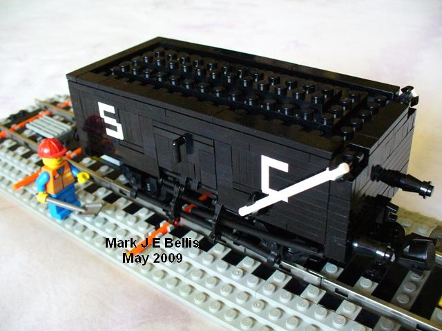
After going to a railway exhibition last Saturday (23rd May), and buying some
books, I was inspired to build some new wagons.
I added working features, such as opening doors, as well as SNOT lettering.
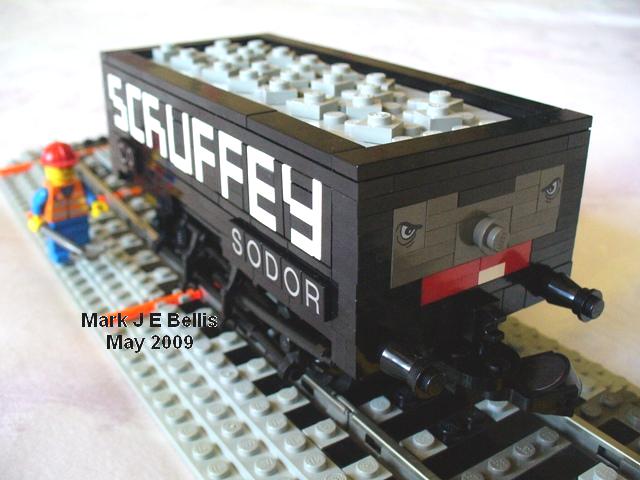
Most are real UK wagons but I also did the Awdry character “Scruffey”.
The new plate modified 1x2 with bar on end is quite a useful piece for
drop-sided wagons. Black droid arms are useful for supporting the tubes
underneath. The tubes represent parts of the brake gear and supports, but
working brakes might have been overkill :classic:
More technical info here:
http://www.brickshelf.com/gallery/mbellis/Trains/Wagons/New-Wagons-May-2009/2009_wagons_info.txt
There are 4 wagons, the first picture of each here:
“Scruffey”:
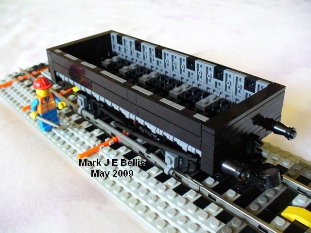
Grampus 12ft wheelbase drop-side wagon:
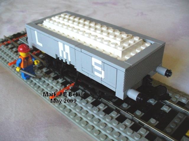
LMS 5-plank open wagon with lime load and opening side doors:
SC coal wagon with opening side and end doors:
Folder when moderated: http://www.brickshelf.com/cgi-bin/gallery.cgi?f=385528
Includes some open-door and underneath pictures too.
Hope you like them.
Mark
Mark Bellis 8mm Scale LEGO Trains
http://www.brickshelf.com/cgi-bin/gallery.cgi?f=62749
|
|
| |
In lugnet.trains, Mark Bellis wrote:
| |
In lugnet.trains, Dave Sterling wrote:
| |
In lugnet.trains, Jonathan Wilson wrote:
| |
We all want new larger radius curves and other things. Also, Big Ben
Bricks, BrickArms and others have been able to successfully mold and sell
new custom parts.
Has anyone ever considered extending this and doing some kind of molding of
new track pieces ourselves? Has anyone ever done some investigation of how
much it would cost for a mold for a larger radius curve or other new track
shapes?
Would people (and e.g. train clubs) be willing to donate towards the
(potentially high) costs for producing such a mold? (my guess is that once
the mold is made, the actual costs of producing the parts would not be huge
in bulk volumes)
|
I think some people have investigated this in the past for 9V and found that
the cost was to great to warrant proceeding. That said, it is probably more
feasible for the ‘RC Track’ since you would not have to deal with the metal
rails.
However, it appears that LEGO might be fixing the track geometry issue with
this nifty new element.
http://www.flickr.com/photos/jastermereel08/3335067544/in/pool-legotrains

Only time will tell though.
-Dave
ToT-LUG
|
With a little modding to the internal curves of the parts shown in the
picture above, it might be possible to support ballast from underneath the
track like this:
http://www.brickshelf.com/gallery/mbellis/Trains/Ballasting-Track/ft_ballast_m_bellis.jpg
Mark
|
Here is a further picture, showing 64 flexible track pieces in set 8867.
The gaps between the two halves of each track piece are smaller than in the
previous picture, and there are fewer studs for attaching ballast:
http://www.aquazona.cz/smf/download/file.php?id=1729&mode=view
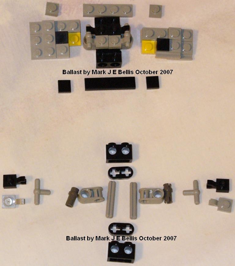
To ballast it means either a bit more modding (4 holes punched per piece, a bit
laborious for 1000 pieces in a layout) or a compromise on ballast width. Take
two 1x4 plate hinges per track piece, one black and one bley or dark bley. Swap
the halves so that each hinge is half black. Attach the hinges to the two studs
in the middle of each track piece. It’s better if the hinges face the inside of
the curve because the hinge can be opened a bit in some cases. This needs two
curves on the layout, each curve using the left halves of one hinge colour and
the right halves of the other colour. This will provide alternate black and
grey stripes to represent sleepers and ballast. Unfortunately the ballast will
not be the full width between the rails but it does have the advantage of not
needing any support from below the track.
I first used bi-colour hinges in ballast on the crossover:
http://www.brickshelf.com/cgi-bin/gallery.cgi?i=3277249
Unfortunately the hinges are not yet available in black, bley or dark bley in
PaB online.
Alternatives with clip plates and rods might work, giving a wider ballast
between the rails, and perhaps enhancing the randomness because grey and black
colours would merge more. It might not be quite so easy to show clear sleepers
though, unless grey clips would look like a small ballast spillage on top of
them, which is OK in the middle 2ft between the rails.
Mark
|
|
|