 | | | | | |
Here’s my drawing of the RCX IR transmission circuit (receiver circuit to follow
soon):
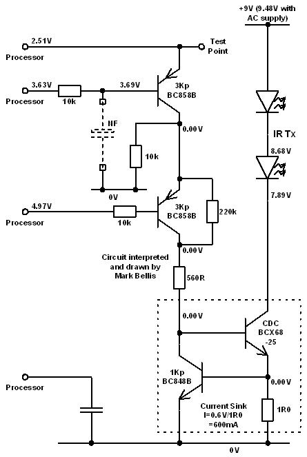
With the voltages as shown, the RCX is not transmitting.
The IR LEDs are powered by a 600mA current sink.
I haven’t measured for waveforms yet - the intermediate voltages may be averages
of pulse trains. The lower transistor input from the processor is turned off by
being pulled up towards +5V (PNP transistors require a low voltage on the base
to turn on)
The CDC transistor has a gain (hfe) of 250, hence the -25 suffix.
This circuit was a bit more difficult since so many tracks seem to go straight
to the processor. If I can glean any more from the H8 data sheet, I’ll add it
later.
Mark
| | | | | | | | | | | | | | |
In lugnet.robotics, Mark Bellis wrote:
| |
Here’s my drawing of the RCX IR transmission circuit (receiver circuit to
follow soon):
|
Thanks for all your work on this Mark! It is very interesting, even for someone
like me with only basic knowledge of electronics. Are you planning to put it all
together on a web page some day?
ROSCO
| | | | | | | | | | | | | | | | |
In lugnet.robotics.rcx, Ross Crawford wrote:
| |
In lugnet.robotics, Mark Bellis wrote:
| |
Here’s my drawing of the RCX IR transmission circuit (receiver circuit to
follow soon):
|
Thanks for all your work on this Mark! It is very interesting, even for
someone like me with only basic knowledge of electronics. Are you planning to
put it all together on a web page some day?
ROSCO
|
For the time being, all the RCX ones are in the same Brickshelf folder, though
obviously this is unavailable for a while whenever I add one.
Code Pilot, RC Tower and other units are in other folders.
Russell Nelson has added links on his mindstorms page:
http://www.crynwr.com/lego-robotics/
It’s a pleasure to be able to add something to the community, and use my
professional skills for my hobby. I suppose I do forward rather than reverse
engineering at work though :-)
This begs another post for another thread about the RCX3...
Speaking of adding circuits, here’s the RCX IR Rx circuit:
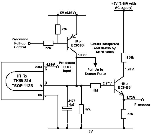
There is surprisingly little to the receiver circuit. The data output from the
receiver device goes straight to the processor.
The +5V pull-up circuit is common to the receiver and the sensor ports. The 3Kp
transistor and the 22k resistors are also on the sensor port circuit. I’ve
added another feed to the processor that hangs off the pull-up. This might be a
signal that tells the processor that both +9V and +5V supplies are present,
which might tell the processor to shut down safely if either supply were
interrupted.
I’ll look at the motor control circuit next, though I expect it will be similar
to the one on the MLX10402 motor driver data sheet.
Mark
| | | | | | |