Subject:
|
Re: The NMRA Trestle Bridge
|
Newsgroups:
|
lugnet.trains
|
Date:
|
Mon, 29 Aug 2005 21:47:19 GMT
|
Viewed:
|
5277 times
|
| |

|
|
In lugnet.trains, Mark Bellis wrote:
| |
In lugnet.trains, Jeramy Spurgeon wrote:
| |
Hello Everyone!
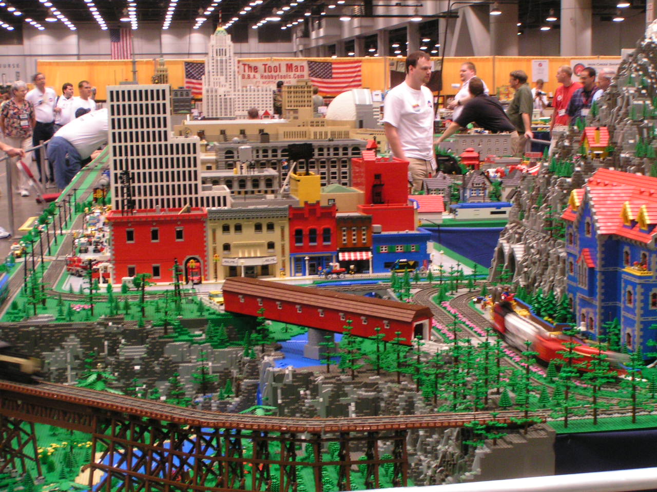
I’ve never posted a MOC on LUGNET before, but I’m not new to building.
First, let me introduce myself: My name is Jeramy Spurgeon, current IndyLUG
president and avid LEGO train fan!
The trestle bridge and surrounding 6 x 6 baseplate area (including the
covered bridge) was built by me starting in February of this year and
finalized in June, prior to the NMRA National Train Show. It was inspired by
a local “O” gauge model club that has a very nice curved trestle bridge on
their layout. I had mentioned at a show we did with them in February, that
that would be a great project to do in LEGO. My fellow club members thought
I was crazy, but the gears of construction began to turn in my head. Here
are some pics of the inspired model:
http://www.brickshelf.com/gallery/bricks/2005kidsexpo/Sunday/image030.jpg
http://www.brickshelf.com/gallery/bricks/2005kidsexpo/Sunday/image029.jpg
I began to work how to make this in LEGO. I had seen several LEGO versions
of trestle bridges, especially inspired by the one built by the PNLTC a few
years ago (links currently unavailable).
It took me a few months to gather all the needed parts, what would we
ALEs/AFOLs do without Bricklink??
The progress pictures are here (with a few new ones added to show how each
individual trestle was made):
http://www.brickshelf.com/cgi-bin/gallery.cgi?f=119785
As you may be able to tell from the pics, I used 1x1 tile with clip on top
with the 1x2 plate with handle to work out the angled beams. 1x1 plates with
headlight clips were used to attach the angled supports. The 1x1 headlight
bricks allow for the tiles and plates to be placed on the side, which is
really where the stability comes from.
A test build in June before the Big Show:
http://www.brickshelf.com/gallery/bricks/NMRA/Preliminary/image010.jpg
which also gives you an idea of the area I built to accomodate the
bridge.This area was designed to compliment the incredible mountain scene
built by my fellow IndyLugger, Brian Darrow:
http://www.brickshelf.com/cgi-bin/gallery.cgi?f=115505
At first, I was concerned about how stable the bridge would be, but after
connecting all of the track and then attaching it to the rock walls, it was
way more stable than I could have imagined!
As for the questions asked in this thread, I just took my inspiration mostle
from the “O” scale bridge and various images found while Googling. I did
decide to create a smaller bridge into the Trestle that crossed the water
because the same questions came to me when designing the bridge. I bypassed
this by creating an area of the bridge that simply went “over” the water
rather than having stanchions stuck into the water itself. This inspiration
came from a picture in an older issue of Model Railroader magazine.
Well, I hope this sheds a little light on the trestle bridge construction
process. I,myself, have never taken really good pictures of it, so I hope
these Brickshelf account owners don’t mind me pointing to some of their
pictures:
http://www.brickshelf.com/gallery/zephyr1934/NMRA-2005/nmra-2005.jpg
http://www.brickshelf.com/gallery/lar/shows/NMRAJuly05/Thursday/dscn5500.jpg
http://www.brickshelf.com/gallery/DecoJim/NMRA2005/indylug05.jpg
Questions?
--Jeramy
|
I like the way you’ve used 1x1 round plates to connect to the slip plates on
the stanchions. They grip the back to back studs better than other plates,
whilst giving a suitable clearance from the stanchions themselves.
How long did it take to set up at the show?
|
Anywhere from 2-3 hours, but that’s not entirely the bridge set-up, I’m
including detailing the countryside as well. Each stanchion is setup then the
track bed attached to the top. The most time consuming part is attaching the
tiles onto the outside. I never seem to do it the same way twice.
| |
Is there a maximum speed imposed on the train, beyond which the bridge might
topple over? (I know American trains often crawl, but passenger trains are
faster).
|
As mentioned, the bridge is surprisingly sturdy. Putting your hand on it and
aggressively trying to budge it doesn’t do much. At full speed, you run the risk
of your train jumping the track before the bridge topples over. I have yet to
have an accident on it, but it’s only been to two shows so far, with another one
coming up in October. Maybe I’ll daredevil some trains around the layout for
test’s sake.
| |
I notice the O-gauge model that inspired you also had concrete bases for its
stanchions.
|
Yep, and that’s what I based it upon, not knowing much about the prototypes.
-Jeramy
|
|
Message is in Reply To:
 | | Re: The NMRA Trestle Bridge
|
| (...) I like the way you've used 1x1 round plates to connect to the slip plates on the stanchions. They grip the back to back studs better than other plates, whilst giving a suitable clearance from the stanchions themselves. How long did it take to (...) (21 years ago, 28-Aug-05, to lugnet.trains, FTX)
|
7 Messages in This Thread:


- Entire Thread on One Page:
- Nested:
All | Brief | Compact | Dots
Linear:
All | Brief | Compact
|
|
|
|