Subject:
|
New point motor with a little SNOT - design submitted for testing
|
Newsgroups:
|
lugnet.trains
|
Date:
|
Wed, 9 Feb 2005 22:33:49 GMT
|
Highlighted:
|
(details)
|
Viewed:
|
2127 times
|
| |

|
|
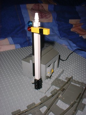
For those who like to experiment with such things, I’ve designed a new point
motor. I’d be grateful if someone can build another one and try it out.
It’s a combination of one of my earlier designs with some elements of Mark
Riley’s control (manipulating the point lever rather than the slider) and Jon
Reynold’s signals, but with my own added SNOT and mechanical miniaturisation.

Click the image for the DAT file. I will render some instructions at some
point, or if someone has a streamlined LPub setup and can do it for me it would
be appreciated. I do have a display module to build in the meantime.
It’s a small footprint, at 8x8 studs, and a quarter of that overlaps the point
lever itself. It meets all my criteria for a point motor, to whit:
1. It’s directional - use positive or negative current to set the direction.
2. It works at full 9V.
3. It’s powerful enough to switch new points without modification.
4. It has a belt drive for overrun protection.
5. It has a physical block to prevent overrun forcing of the point mechanism.
The design is intended to look like a small trackside bunker. You can remove
the roof and lever off the end wall, then the motor and the first pulley
(connected by two yellow belt drives) lift out together.
I found that instead of trying to use half-bushes and pulleys in the belt drive
to get a 1:3 ratio, you get more power out of a belt drive using simply all
pulleys. The larger contact area with the belt makes all the difference. And
Lego belts really are best. You can use similarly sized elastic bands, but they
tend to stretch more and can slip off the pulleys.
I use a 1:2 (8:16) gearing inside to add more power, so it’s not the fastest
switcher around. But, it keeps a low profile by having an inverted rack driven
from below. Using those technic connectors is another innovation to get the
hole in the right place, the SNOT rack, and the half-plate height adjustment so
the top tiles are at the right height. It’s the 1x2 tile on top of the sliding
shuttle that stops it pushing too far. Having the gearing alongside the motor,
and using the end of the motor as part of the shuttle guide wall all help reduce
the footprint size too.
I included some technic 1-wide plates in the base, so that the holes in the ends
of these plates get a very firm grip on the point itself.
Finally, there’s a rather fetching signal on the end.
You can build the opposite-hand version to the one in the picture, and the
signal is optional. Just use a 1x4 plate where the 4x4 plate attaches, and a
6-stud axle instead of the 8 so it doesn’t protrude. If you fit that to the
point, you’ll find it doesn’t extend beyond the end of the point. So, you could
fit two of these motors on back-to-back points.
Anyway, any comments from someone who has the time to build and test one of
these would be appreciated.
Thanks,
Jason Railton
More on motorising points can be found at
FreeLug.
|
|
Message has 1 Reply:
2 Messages in This Thread:
  
- Entire Thread on One Page:
- Nested:
All | Brief | Compact | Dots
Linear:
All | Brief | Compact
|
|
|
|