| |
In lugnet.technic, Jetro de Chateau wrote:
| |
In lugnet.technic, Mark Bellis wrote:
| |
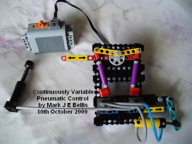
To celebrate, here are the pictures of my latest pneumatic system.
It allows the cylinder to be commanded to any position.
• not just the two ends
• not just two ends and one position in the middle
• yes, any variable position within its travel!

|
Thank you for sharing this. Next up: implementing this in an automated
system...
Jetro
|
Here’s a video tutorial that explains how it works:
http://www.youtube.com/profile?user=mbellisbrickmocs#p/u/0/9jv73J8-4Zw
The demonstration model is an automated system in itself. It is the inner loop
of a control system. The (optional) outer loop would use feedback from a driven
device to move the red beam, but not all applications need an outer loop. The
cylinder pictured can be the cylinder that drives the model function, or
parallel cylinders from the same hoses can do that. It could be most of the
system or a building block for a larger system. I like the fact that few enough
pneumatic elements are used that it should be accessible to more people.
I thought of a few applications for the system:
- Truck suspension including centre lift or tag axle (redistribute the force to
the non-lifting wheels)
- With higher feedback gain, a show car bouncy
suspension or monster truck jumping function.
- Anti-roll suspension, putting
more pressure to the outside wheels when cornering.
- Power steering (add an
axle across the system, to keep the wheels in sync with the steering wheel).
-
Robot leg force balancing or body weight distribution for a biped.
- NXT
precise control of pneumatics. The NXT motor with its shaft encoder can tell
the position of the red beam if driven by a worm and rack. Therefore the NXT
can know what the cylinder position set point is and can use open loop control
with a suitable delay for the actual cylinder position.
I have a few more ideas for multiple applications in one model, which I will
think about further. A smooth drive steam engine should be possible, varying
the pseudo-steam pressure and hence implementing a real steam loco reverser
speed control function. The levers in the demonstration model do a similar
thing to the valve gear in a steam engine, adding together the piston position
and the reverser position. The gains of input, dither and feedback would be
adjusted for each application.
Hope you like the video, and find it explains things OK. I didn’t write a
script first, so a few “um”s and “er”s crept in. I was surprised it ended up
being 10 minutes long. Glad I found some free software to convert .mov files to
.mp4 as it cut the file size by 80%.
Enjoy!
Mark
======================================================================================================================================
Mark J E Bellis LEGO Pneumatics
http://www.brickshelf.com/cgi-bin/gallery.cgi?f=82736
|
|
Message has 1 Reply:
Message is in Reply To:
6 Messages in This Thread:
        
   
- Entire Thread on One Page:
- Nested:
All | Brief | Compact | Dots
Linear:
All | Brief | Compact
This Message and its Replies on One Page:
- Nested:
All | Brief | Compact | Dots
Linear:
All | Brief | Compact
|
|
|
|