| |
i picked up several 8376 Hot flame RC cars at my local radio shack
yesterday. (they were on sale for $40) and immediately opened one of the
rc receiver units. i have posted pictures in my bricklink
directory: http://www.brickshelf.com/cgi-bin/gallery.cgi?f=79385
does anyone have pictures of the inside of the 6272 so i can compare it to
the 6292? i'm wondering if it is possible to add the auxiliary output to
the 6292.
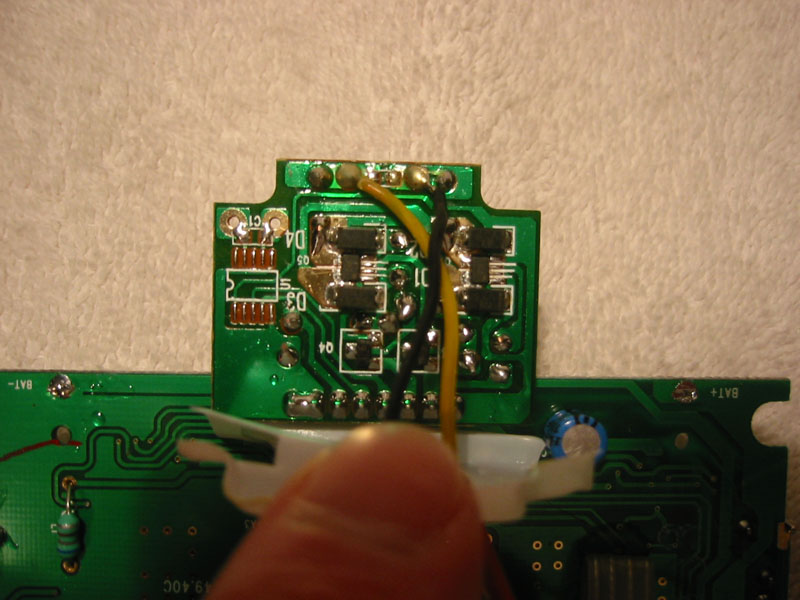
what is the missing chip in this picture? an h-bridge of some sort?
http://www.brickshelf.com/gallery/bobko/6293/img_5514.jpg
should it be the chip in the bottom left corner of this picture?
http://www.brickshelf.com/gallery/bobko/6293/img_5518.jpg the chip is
marked 1930 306.
i'm guessing that the rc controller would need to be modified so that the
paddles do not reverse the motors when pressed.
i know that it is a far stretch but is it possible that all you would need
to do is add the missing chip to add the auxiliary output?
thanks,
bob
Bob Kojima
ko@fial.com
Fial Incorporated
Telecom Monitoring Solutions
4343 SW Corbett Ave
Portland, OR 97239
503.227.7083
http://www.fial.com
|
|
| |
In lugnet.technic, Bob Kojima wrote:
> i picked up several 8376 Hot flame RC cars at my local radio shack
> yesterday. (they were on sale for $40) and immediately opened one of the
> rc receiver units. i have posted pictures in my bricklink
> directory: http://www.brickshelf.com/cgi-bin/gallery.cgi?f=79385
>
> does anyone have pictures of the inside of the 6272 so i can compare it to
> the 6292? i'm wondering if it is possible to add the auxiliary output to
> the 6292.
>
> what is the missing chip in this picture? an h-bridge of some sort?
> http://www.brickshelf.com/gallery/bobko/6293/img_5514.jpg
>
> should it be the chip in the bottom left corner of this picture?
> http://www.brickshelf.com/gallery/bobko/6293/img_5518.jpg the chip is
> marked 1930 306.
>
> i'm guessing that the rc controller would need to be modified so that the
> paddles do not reverse the motors when pressed.
>
> i know that it is a far stretch but is it possible that all you would need
> to do is add the missing chip to add the auxiliary output?
Hi Bob,
I opened two of my receivers, one was from set 8376 Hot Flame and the other was
from set 8475 RC Buggy (I actually purchased this second receiver from BrickLink
just to get the third output).
The first thing I noticed is that the motor control daughter boards differ by
more than just the missing chip on the Hot Flame version. On the RC Buggy
board, most of the H-bridge components are on the other side of the board (using
thru-hole components - the Hot Flame using surface mount components for the
H-bridge).
However, your hunch about the 1930 chip is correct as the RC Buggy has one of
these chips in the same location as the empty chip pad on the Hot Flame version.
The differences in the boards could be that Lego decided to switch from
thru-hole to surface mount components at some point and there very well could be
RC Buggy receivers with a daughter board similar to the Hot Flame (but with the
addition of the 1930 chip).
Now for the not so encouraging news: I tested the signals going to the daughter
boards. On the RC Buggy version, the center two pins on the connector are
controlled by the two paddles on the transmitter - they change between 0V and 5V
as each paddle is pressed. On the Hot Flame version, these pins just remain at
0V and the pins that control forward/reverse change when the paddles are
pressed.
So, I'm thinking that if there isn't something simple like a jumper on the main
board to change the paddle behaviour (a slim possibility - and I haven't noticed
it yet myself), there may not be an easy way to add the third output.
Mark
|
|
| |
thanks for checking Mark! that is more help than i expected. too bad it's
not going to work. guess i'm going to have to buy another receiver from
bricklink if i really want the extra output.
bob
At 10:22 PM 4/14/2004 +0000, you wrote:
> In lugnet.technic, Bob Kojima wrote:
> > i picked up several 8376 Hot flame RC cars at my local radio shack
> > yesterday. (they were on sale for $40) and immediately opened one of the
> > rc receiver units. i have posted pictures in my bricklink
> > directory: http://www.brickshelf.com/cgi-bin/gallery.cgi?f=79385
> >
> > does anyone have pictures of the inside of the 6272 so i can compare it to
> > the 6292? i'm wondering if it is possible to add the auxiliary output to
> > the 6292.
> >
> > what is the missing chip in this picture? an h-bridge of some sort?
> > http://www.brickshelf.com/gallery/bobko/6293/img_5514.jpg
> >
> > should it be the chip in the bottom left corner of this picture?
> > http://www.brickshelf.com/gallery/bobko/6293/img_5518.jpg the chip is
> > marked 1930 306.
> >
> > i'm guessing that the rc controller would need to be modified so that the
> > paddles do not reverse the motors when pressed.
> >
> > i know that it is a far stretch but is it possible that all you would need
> > to do is add the missing chip to add the auxiliary output?
>
> Hi Bob,
>
> I opened two of my receivers, one was from set 8376 Hot Flame and the
> other was
> from set 8475 RC Buggy (I actually purchased this second receiver from
> BrickLink
> just to get the third output).
>
> The first thing I noticed is that the motor control daughter boards differ by
> more than just the missing chip on the Hot Flame version. On the RC Buggy
> board, most of the H-bridge components are on the other side of the board
> (using
> thru-hole components - the Hot Flame using surface mount components for the
> H-bridge).
>
> However, your hunch about the 1930 chip is correct as the RC Buggy has one of
> these chips in the same location as the empty chip pad on the Hot Flame
> version.
> The differences in the boards could be that Lego decided to switch from
> thru-hole to surface mount components at some point and there very well
> could be
> RC Buggy receivers with a daughter board similar to the Hot Flame (but
> with the
> addition of the 1930 chip).
>
> Now for the not so encouraging news: I tested the signals going to the
> daughter
> boards. On the RC Buggy version, the center two pins on the connector are
> controlled by the two paddles on the transmitter - they change between 0V
> and 5V
> as each paddle is pressed. On the Hot Flame version, these pins just
> remain at
> 0V and the pins that control forward/reverse change when the paddles are
> pressed.
>
> So, I'm thinking that if there isn't something simple like a jumper on the
> main
> board to change the paddle behaviour (a slim possibility - and I haven't
> noticed
> it yet myself), there may not be an easy way to add the third output.
>
> Mark
Bob Kojima
ko@fial.com
Fial Incorporated
Telecom Monitoring Solutions
4343 SW Corbett Ave
Portland, OR 97239
503.227.7083
http://www.fial.com
|
|
|