| |
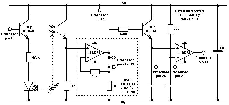
Here’s my drawing of the Code Pilot light sensor circuit:

Looking at the components used, there’s no reason why a similar circuit couldn’t
be used as an RCX sensor, though I see the real one is more sophisticated:
http://www.plazaearth.com/usr/gasperi/light.htm
In the Code Pilot, the processor controls the LED via the top left transistor.
470 ohms is a typical value to use with a 5V supply, giving just over 10mA to
the LED. Many IR communication devices use a much higher pulsed current at low
duty cycle, but the Code Pilot light sensor is designed for close range use with
the bar code sheet or tacho wheel, so this is unnecessary.
The first half of the LM358 dual op-amp is a non-inverting amplifier with a gain
of 19 (1+(18k/1k)). The processor can either use the ac signal or pass it on to
the second half of the op-amp, which is used as a comparator. Here the
capacitors remove the ac component of the signal, so that the output doesn’t
oscillate.
Perhaps the comparator is used with the wheel VLL codes, since the reflected
light from a wheel at standard distance is a known amount and therefore produces
a known signal so that the comparator threshold can be set mid-way between the
two signals from a reflective part of the wheel and from a gap in the wheel.
The 5V supply is provided by an LM2936M-5 voltage regulator - a 3-pin regulator
in an 8-pin SOIC package, using four pins for ground.
PLMKWYT
Mark
|
|
1 Message in This Thread:

- Entire Thread on One Page:
- Nested:
All | Brief | Compact | Dots
Linear:
All | Brief | Compact
|
|
|
|