| |
In lugnet.technic, Brian H. Nielsen wrote:
> In lugnet.announce.moc, Kevin L. Clague wrote:
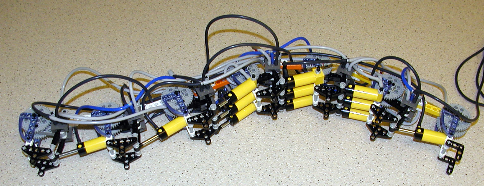
> > I'm pleased to announce my latest pneumatic creature, an inchworm. Inchworm is
> > much larger than an inch, but its body moves using a traveling wave like
> > inchworms do.
> >
> > You can see the basic shape of my inchworm:
> >
> > http://www.brickshelf.com/gallery/kclague/Inchworm/p7020052.jpg
> >
> > It is composed of 6 pneumatic segments, four are always expanded, and two are
> > always compressed. Over time segments are contracted and expanded in a
> > coordinated fashion so the compressions move forward on the inchworm. Once the
> > compressions reach the head of the inchworm, they move to the back of the
> > inchworm and start the process over.
> >
> > The middle segments had a hard time bending the inchworm enough to get the
> > pistons to close, so I added some extra pistons to make things work more
> > reliably. The original design was 6 pistons and twelve switches. I had to add
> > some more pistons in the middle.
> >
> > This image shows inchworm on its side:
> >
> > http://www.brickshelf.com/gallery/kclague/Inchworm/p7020057.jpg
> >
> > I have mpeg movies of it walking that play here on my local machine, but when I
> > upload them to bricklink they end up garbled. I guess I'll have to wrestle with
> > that.
> >
> > Inchworm is my wife's all time favorite MOC.
> >
> > PLMKWYT
>
> Nice concept to model in pneumatics. I'd love to see the MPG when you get it
> uploaded. I assume you implemented the compression with logic gates cascaded
> along the body.
I made the movies smaller and now they work. Here is the whole inchworm going
through one cycle.
http://www.brickshelf.com/gallery/kclague/Inchworm/inchworm_whole.mpg
Here is a close up of the compression part of the wave as it travels from the
back of the inchworm to the front:
http://www.brickshelf.com/gallery/kclague/Inchworm/inchworm_closeup.mpg
On my flight to Boston for work two weeks ago I had flash of insight into how to
design pneumatic circuits that follow repeated patterns. This picture shows my
design of the circuitry. It is quite terse.
Step 1 is to lay out the timing truth table shown in this picture:
http://www.brickshelf.com/gallery/kclague/Inchworm/inchworm_table.jpg
Each new row in the table is a new time unit. Each column in the table is a
piston in the inchworm. A 0 means the piston is compressed. A 1 means the
piston is expanded. Notice that there are seven time units listed, and that the
pistons are in the same pattern in the seventh time unit as the first.
In Step 2, I redraw the truth table as a timing diagram. The problem I used to
have in this step was that I drew them out as square waves, which wasn't very
informative. On the flight to Boston, I thought to draw the transitions as
diagnonal lines indicating that it takes time for the piston to expand or
contract.
The second phase of step 2 is to identify which pistons become stable at the end
of each time period. In the first (idealized) time period, E transitions from 1
to 0, and C transitions from 0 to 1. At the end of the (idealized) time period,
both stablize. In the second time period, F transitions from 1 to 0, and D
transitions from 0 to 1. I draw a circle where the signal goes stable, and a
line between stablized circles. This ends up as an AND of the transitioning
pistons that I call synchronization points. After identifying all the
synchronization points, I move onto the last phase of step 2.
In this phase, we identify what pistons change when a synchronization point is
met. When C finishes transitioning from 0 to 1 and E finishes transitioning to
0, D starts transitioning from 0 to 1, and F starts transitioning from 1 to 0.
I draw curved arrows from the synchronizing pistons of a time period to the
pistons that change in the next time period. This shows us the relationships
between pistons.
Is step 3, we identify the formula of the synchronization points identifies in
step 2. Each synchronization formula ends up being an AND of the pistons that
go stable. For example in the first time period E transitions to 0 and C
transitions to 1. This maps to the formula C AND NOT E (so the formula ends up
being true when we're synchronized.) Following this pattern we end up with 6
synchronization formula.
In step 4, we identify which synchronization terms feed the pistons expand and
contract ports. In the case of piston A, we can see that it expands due to
synchronization point S4, and contracts because of synchronization point S2.
Completing step 4 finalizes the pneumatic circuit design.
Each piston has two switches. The first switch (value switch) takes in pressure
from the pumps, and feeds pressure out a port when the piston that controls it
is expanded. This provides the value A used in out synchronization terms. The
second switch of a given piston provides the AND function. Piston A's value
(from the value switch) is ANDED with NOT C to create synchronization point S5
(meaning A's value switch output is run into the center port of piston C's AND
switch). Note that E's value switch output is run into the center port of
piston A's AND switch to create S3.
For the AND switches, the port used is the port that receives pressure when its
controlling piston is contracted. This gives us the AND NOT part.
Once we have the AND NOT things (synchronization points) hooked up, we can then
run those values to pistons. A AND NOT C (S5) causes piston B to expand, and
piston D to contract, so we must connec the A AND NOT C to piston B's expand
port (the base of the piston), and piston D's contract port (the top of the
piston).
Once we've got all these things hooked up (pistons hooked mechanically to
switches), switches hooked pneumatically to switches, and swtiches hooked back
to pistons, we've completed the implementation of our asynchronization of our
pneumatic circuit.
Sorry about going on and on, but I've been trying to come up with something like
this for quite a while. The algorithm is general beyond just the design of
inchworm.
There are a few caveates, but I'll only go into them if someone is interested.
Kevin
|
|
Message is in Reply To:
8 Messages in This Thread:
")  
 

- Entire Thread on One Page:
- Nested:
All | Brief | Compact | Dots
Linear:
All | Brief | Compact
|
|
|
|